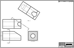
Learning and Applying Solid Edge V20 Step-by-Step

Objectives:
Create a simple sketch using the Sketch command
Extrude a sketch into a solid using the Model command
Create an Orthographic view using the Drawing View Wizard
Create an Isometric View
Chapter 3 includes instruction on how to design the parts shown below.

Start Solid Edge by referring to "Chapter 1 Getting Started".
After Solid Edge is running, begin a new sketch.
Move the cursor to the upper left corner of the screen and left click on Line as shown in Figure 1.
Move the cursor somewhere in the lower left portion of the screen and left click once. This will be the beginning end point of a line as shown in Figure 2.
Move the cursor to the right and left click once as shown in Figure 3.
Move the cursor upward and left click once as shown in Figure 4.
Move the cursor to the left and wait for dashes to appear. Left click once as shown in Figure 5.
Move the cursor back to the original starting end point. A red dot will appear. Left click once. Your screen should look similar to Figure 6.
Move the cursor to the upper middle portion of the screen and left click on SmartDimension as shown in Figure 7.
After selecting SmartDimension move the cursor over the bottom horizontal line until it turns red as shown in Figure 8. Select the line by left clicking anywhere on the line or on each of the...