Modern Control Systems: An Introduction
1.3: BLOCK-DIAGRAM REPRESENTATION OF A GENERAL CONTROL SYSTEM

1.3 BLOCK-DIAGRAM REPRESENTATION OF A GENERAL CONTROL SYSTEM

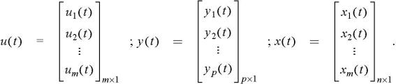
In state-variable formulation of a system, the state-variables are usually represented by x 1( t), x 2( t), x 3( t) ; the inputs by u 1( t), u 2( t), u 3( t), ; and the outputs by y 1( t), y 2( t) The state-space representation of a system that has m inputs, p outputs, and n-state variables may be visualized in block-diagram form as shown in Figure 1.1. For notational economy, the different variables may be represented by the input vector u( t), output vector y( t), and the state vector x( t), where


UNLIMITED FREE
ACCESS
TO THE WORLD'S BEST IDEAS

SUBMIT
Already a GlobalSpec user? Log in.

This is embarrasing...

An error occurred while processing the form. Please try again in a few minutes.

Customize Your GlobalSpec Experience

Category: Programmable Logic Controllers (PLC)
Finish!
Privacy Policy

This is embarrasing...

An error occurred while processing the form. Please try again in a few minutes.