Motor Control Electronics Handbook
This up-to-the-minute guide provides you with motor control fundamentals and progressive design tips, as well as the latest in electronics technology.
Richard J. Valentine
Motorola Semiconductor Products
Testing an electronic motor control design for the first time can be an exciting event, the culmination of much effort and time. It can be very exasperating as well, since power semiconductors will fail in less than 100 millionths of a second, allowing little time to figure out what went wrong. In this chapter we will discuss various methods to detect problems and lessen the chances for unexpected power stage device failures.
The layout and equipment of a motor test lab should be thoughtfully planned and organized. It should include a controlled power source, dynamometer, oscilloscopes, temperature meters, and digital multimeters. A computer development station should also be located in close proximity to the motor's electronics.
The first consideration for a motor test lab is its location. The motor dynamometer (dyno) needs to be accessible with motor-handling equipment. A large dyno may require a water supply and drain hookup. Smaller dynos usually are fan-cooled and may require an inlet and outlet for outside air. Figure 17.1 illustrates a lab layout for testing medium-power electronic-controlled motors. Note that the benches are arranged in a U-shaped configuration, which allows plenty of work surface while keeping everything close at hand.
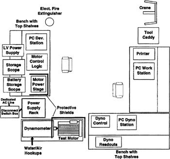
Room for large power supplies is another consideration. Instead of running the motor control unit directly off the AC power line, large...