Radar Systems for Technicians

Combining historical insight and technical information, this text takes the reader as far back as original World War II concepts to illustrate the logical reasoning behind state-of-the-art radar designs.
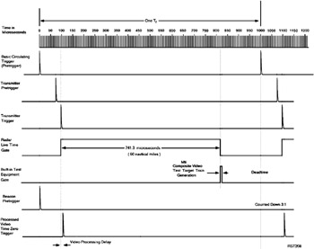
The synchronizer is the source of all timing signals for a radar system. Synchronizers may differ considerably from one radar system to another, but some fundamental design concepts applicable to many of them will be discussed here. Figure 9 1 is a simple diagram of some basic timing signals required of an ASR radar. Triggers and gates for use throughout the radar system may be produced by the synchronizer, or by other units which rely upon the synchronizer for timing triggers. Among the various timing signals are the transmitter triggers, the coho gate in magnetron systems, stc triggers, display triggers, live-time gates to enable the receiver outputs for 741 ?secs (for 60-mile ASR radars), or 2471 ?secs (for 200-mile ARSR radars), deadtime triggers to initiate built-in-test (BIT) functions, and many others. Satisfactory operation of the mti system places stringent requirements on the synchronizer design and stability that would not otherwise be necessary.
The mti system depends upon T r-to-T r, pulse-to-pulse, comparisons of bipolar video to achieve cancellation of zero- and near-zero-Doppler clutter targets in the comparator circuit of the canceler. To prevent residue, which may be described as, uncanceled portions of stationary targets, it is absolutely essential that the one-T r-delayed target occur in exact time coincidence with the undelayed target. In analog systems, engineering such a system was no small matter. The amount of delay had to be precisely the same as...