In Fig. 4.40 the product shape of the seventh pass is shown with the incoming product shape of the sixth pass in phantom lines.
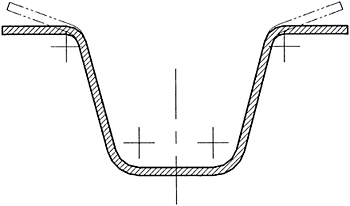 Fig. 4.40
 If the shoulder gap detail is retained in the seventh pass to ensure correct setting of the material gap as changes occur in the material thickness being processed, the shoulder detail is on the bottom roll, as in Fig. 4.41, and the material gap is at .081 to accommodate the maximum material thickness.
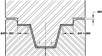 Fig. 4.41
 As was made clear in Chapter 2, for material thickness less than the maximum, the looseness at the tangent point of the radius fails to set the bend, introducing angular error because the final bend is incomplete (see Fig 2.11 and Fig 2.12). At minimum material thickness of .068, there would be a result similar to that shown in Fig. 4.42 in which all of the bends are shown in phantom, 4 degrees open.
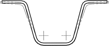 Fig. 4.42
 If the product requirements and tolerances are sufficiently loose, this could be acceptable, and the roll configuration of Fig. 4.41 would be appropriate. If the product application requires tighter tolerances, a different design approach must be found to get an acceptable product.
One method that has been used after the finish station is an overbending station followed by a repeat finish station to return to the desired end result The problem here is that the amount of overbend required is a judgement call and, furthermore, the amount of overbend required is...