Safety Instrumented Systems: Design, Analysis, and Justification, 2nd Edition

8.11: Analysis of a Non-Redundant PLC System

8.11 Analysis of a Non-Redundant PLC System

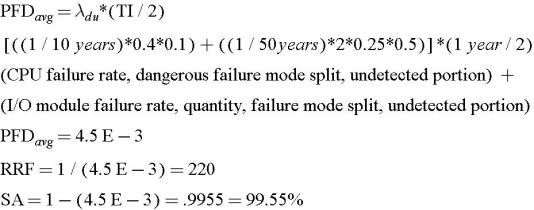
What if we were to replace the relay system with a general purpose PLC? To be consistent with the I/O count of the relay examples, we can consider a PLC with 1 input and 1 output module. Do not attempt to split the calculation down to individual channels of a module, as there are usually common components on a board that could make the entire module fail. Let's assume:

CPU MTBF = 10 years

I/O module MTBF = 50 years

CPU safe failure mode split = 60%

I/O module safe failure mode split = 75%

We can also assume a dual redundant power supply. The probability of a simultaneous failure of two supplies would be orders of magnitude below the simplex components, so essentially it may be ignored in the model.


Let's now assume 90% diagnostic coverage of the CPU and 50% for the I/O. The following assumes that the PLC is actually manually tested yearly.


So, the nuisance trip performance is about the same as the relays, but the PLC is less safe than relays by one order of magnitude! This tends to take a lot of people by surprise. Remember that we're assuming the PLC is actually fully tested manually once per year (which is an overly optimistic assumption for many systems). An I/O module diagnostic coverage of 50% is also an optimistic assumption for many general purpose systems. This is not saying anything negative about PLCs. General purpose...

UNLIMITED FREE
ACCESS
TO THE WORLD'S BEST IDEAS

SUBMIT
Already a GlobalSpec user? Log in.

This is embarrasing...

An error occurred while processing the form. Please try again in a few minutes.

Customize Your GlobalSpec Experience

Category: IndustryPack® Modules
Finish!
Privacy Policy

This is embarrasing...

An error occurred while processing the form. Please try again in a few minutes.