Schaum's Outline of Theory and Problems of Electronic Communication, Second Edition
Chapter 1: Characteristics of Tuned LC Circuits

INTRODUCTION

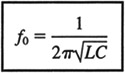
For any series or parallel LC circuit, the inductive reactance X L and capacitive reactance X C will be equal at some frequency. The frequency at which X L = X C is called the resonant frequency. When the values of L and C are known, the resonant frequency can be calculated as:

(1.1)

where f 0 represents the resonant frequency.

In general, large values of L and C provide a relatively low resonant frequency, whereas smaller values of L and C provide a higher resonant frequency. The most common application of resonance is in radio-frequency (RF) circuits where tuning is important. Tuning refers to an LC circuit's ability to provide maximum voltage output at the resonant frequency compared with the voltage output at frequencies either above or below resonance. More specifically, tuning is used in RF circuits when it is desired to pass only a specific band or channel of frequencies while at the same time completely rejecting or blocking all others. The use of tuned LC circuits is found in every television, video cassette recorder (VCR), AM/FM receiver, and satellite to name just a few of the more popular applications.

1.1 CHARACTERISTICS OF A SERIES RESONANT LC CIRCUIT

Figure 1-1 shows a series LC circuit. The series resistance r s is a representation of the coil's own internal resistance. Because the circuit does contain some series resistance, it can be considered a series RLC circuit.

UNLIMITED FREE
ACCESS
TO THE WORLD'S BEST IDEAS

SUBMIT
Already a GlobalSpec user? Log in.

This is embarrasing...

An error occurred while processing the form. Please try again in a few minutes.

Customize Your GlobalSpec Experience

Category: RF Inductors
Finish!
Privacy Policy

This is embarrasing...

An error occurred while processing the form. Please try again in a few minutes.