Schaum's Outline of Theory and Problems of Electronic Communication, Second Edition
Let us apply our knowledge of oscillator fundamentals to some commonly used oscillator circuits. Figure 2-2( a) shows a popular circuit known as a Hartley oscillator. Its identifiable feature is the tapped coil in the LC tank circuit. Notice that the coil's tap point is grounded.
The amplifier portion of the oscillator is a common-emitter amplifier. Therefore, the ac base voltage and ac collector voltage are 180 out of phase. This means that the feedback network must provide an additional 180 phase shift so that the feedback voltage is of the correct phase to sustain oscillations. To help you understand the circuit's operation, it has been redrawn in Fig. 2-2( b). Notice that L 1 is in parallel with L 2 and C 3 in series. At the resonant frequency of the tank circuit, the net reactance of the L 2 C 3 branch appears capacitive. Also, the net capacitive reactance of the L 2 C 3 branch equals the inductive reactance of the L 1 branch. This gives us the following mathematical relationship.
Rearranging terms we have:
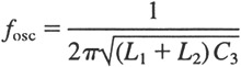
Therefore, the frequency of oscillation, labeled f osc, equals the frequency at which
.
| (2.9) | |
As you can see in Fig. 2-2( b), the feedback voltage v fb driving the base of the transistor is developed across the inductance L 2. Similarly, the output voltage is developed across the inductance L 1.