Schaum's Outline of Theory and Problems of Electronic Communication, Second Edition
2.1: OSCILLATOR FUNDAMENTALS

2.1 OSCILLATOR FUNDAMENTALS

Figure 2-1( a) shows the block diagram of an oscillator containing an amplifier and a feedback network. The output voltage V out from the amplifier is calculated as:

(2.1)

where V in represents the total input voltage applied to the amplifier.


Figure 2-1

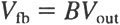
A portion of the output voltage is fed back to the input of the amplifier through the feedback network. The fractional part of the output voltage which is fed back to the input is called the feedback voltage and is designated V fb. The ratio of feedback voltage V fb to output voltage V out is called the feedback fraction and is designated B. The feedback fraction can be expressed as:

(2.2)

Rearranging Eq. (2.2) gives us:

(2.3)

Equation (2.3) clearly states that the feedback voltage is a fractional part of the output voltage. As you can see in Fig. 2-1( a), the feedback voltage V fb is in series with the source voltage V S. If the phase of the feedback voltage is negative, then a portion of V S will be cancelled, in which case the output voltage will be reduced in amplitude. If the phase of the feedback voltage is positive, however, then the input voltage V in is larger than with V S alone. All oscillators must use positive feedback to sustain oscillations. Assuming the feedback voltage is positive in Fig. 2-1( a), the actual...

UNLIMITED FREE
ACCESS
TO THE WORLD'S BEST IDEAS

SUBMIT
Already a GlobalSpec user? Log in.

This is embarrasing...

An error occurred while processing the form. Please try again in a few minutes.

Customize Your GlobalSpec Experience

Category: Voltage-to-Frequency Converter Chips
Finish!
Privacy Policy

This is embarrasing...

An error occurred while processing the form. Please try again in a few minutes.