Torsional Vibration of Turbomachinery
Including application case studies and in-depth interpretation of computer-generated results, this book offers practical answers to preventing excessive damage, failure and noise due to vibrations in machines.
This appendix shows by means of a simple example the way in which a multispeed geared system is transformed into an equivalent single-speed system.
The equivalent system must be constructed to have identical torsional natural frequencies to the geared system. The geared system mode shapes and forced response values are derived from the results from the equivalent system using the transforms that are developed in this appendix.
Figure A.1 shows a simple geared torsional model for illustration purposes with speed increase gears I 2 and I 3 between two rotors, I 1 and I 4.
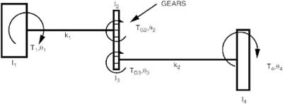
The rotor system I 3- I 4 rotates N times faster than the rotor system I 1- I 2, as a result of the gears. Hence the velocity ratio of I 1- I 2 is 1 and that of I 3- I 4 is N.
Angles ? 1 through ? 4 are the rotational displacements at each rotor or gear location. T 1 and T 4 are applied torques acting on rotors 1 and 4, respectively. T G 2 and T G 3 are gear mesh torques acting on gears I 2 and I 3, respectively. k 1 and k 2 are the shaft stiffnesses.
Figure A.2 shows the equivalent single speed model where J 1, J 2, and J 4


