Practical Power System Protection

Providing both the underpinning knowledge and basic calculations needed to understand, specify, use and maintain power protection systems, this book also covers the practical techniques required on a daily basis.
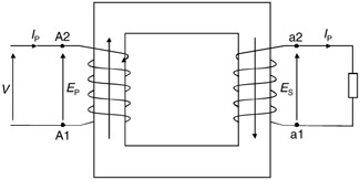
A transformer consists of two windings viz., primary and secondary coupled to a common magnetic core. International standards define the polarity of the primary and secondary windings sharing the same magnetic circuit as follows.
If the core flux induces an instantaneous emf from a low-number terminal to a high-number terminal in one winding, then the direction of induced emf in all other windings linked by that flux will also be from a low-number terminal to a high-number terminal. In the following sketch the induced emf on primary winding E p is from A1 to A2 in the A phase when a primary voltage V is applied across A as shown.
The secondary emf E s is also from a1 to a2 in secondary a phase (see Figure 15.1). From the laws of induction, it will be seen that the current flow in the windings is in the opposite direction.
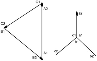
Transformer windings can be connected either in a star (Y) or delta (D) configuration, bearing in mind that each phase will be displaced 120 from the other.
Figures 15.2 and 15.3 show the three windings of a three-phase core type transformer. This shows the primary connected in delta while the secondary windings are connected in star. The vectorial representation of primary and secondary voltages are also indicated.