4.1 INVERTING AMPLIFIER
In an inverting amplifier, the input signal is given to the inverting input terminal and the non-inverting input terminal is connected to the ground. This configuration is shown in Figure 4.1.
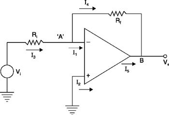 Figure 4.1: Inverting amplifier.
 The analysis will be done assuming ideal op-amp characteristics (refer to section 3.2).
The current from the op-amp input terminals is zero, i.e., I 1 = 0 and I 2 = 0.
The gain of the op-amp is infinity. Therefore, to have a finite output, the input voltage difference between the two input terminals should be zero.
| (4.1) | 
|
The voltage at the non-inverting input terminal is zero volts because it is grounded. Therefore, the voltage at node ' A,' i.e., at the inverting input terminal, is also zero volts.
| (4.2) | 
|
Writing Kirchhoff's Current Law at node ' A' yields
Knowing that I 1 = 0 yields
| (4.3) | 
|
Calculate the current through resistance R i:
Substitute equation (4.2) in this:
| (4.4) | 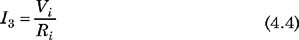
|
Calculate the current through resistance R f:
Substitute equation (4.2) in this:
Solve for V o:
Substitute equation (4.3):
Substitute equation (4.4):
| (4.5) | 
|
This is the relationship between V o, the output voltage, and V i, the input voltage.
In equation (4.5), the minus sign indicates that there is a phase shift of 180 ? between input and output.
Equation (4.5) can be rearranged as
| (4.6) | 
|
The conventional equation for voltage gain is
Substitute equation (4.6):
| (4.7) | 
|
The magnitude...