4.2 NON-INVERTING AMPLIFIER
In a non-inverting amplifier, the input signal is given to the non-inverting input terminal and the inverting input terminal is connected to the ground. This configuration is shown in Figure 4.3.
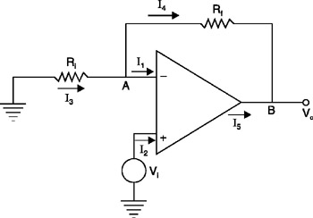 Figure 4.3: Non-inverting amplifier.
 The analysis will be done assuming ideal op-amp characteristics, as done for the inverting amplifier.
The current from the op-amp input terminals is zero.
| (4.9) | 
|
| (4.10) | 
|
The gain of the op-amp is infinity. To have a finite output, the input voltage difference between the two input terminals should be zero. Since the voltage at the non-inverting terminal is V i, the voltage at the inverting terminal must also be V i to satisfy this property. Therefore, the voltage at node ' A' is
| (4.11) | 
|
Writing Kirchhoff's Current Law at node ' A' yields
Substitute equation (4.9) in this:
| (4.12) | 
|
Calculate the current through resistance R i:
Solve for V A:
| (4.13) | 
|
Calculate the current through resistance R f:
Substitute equation (4.11) here:
Substitute equation (4.12) here:
Substitute equation (4.13) here:
| (4.14) | 
|
From equation (4.13) in terms of V A, I 3 can be written.
By doing so, equation (4.14) can be rewritten as:
Substitute equation (4.11) here:
| (4.15) | 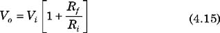
|
Equation (4.15) gives the relationship between the output voltage and the input voltage.
Unlike equation (4.5), equation (4.15) has no minus sign, which indicates that there is no phase shift between input and output.
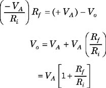
Equation (4.15) can be rearranged as:
| (4.16) | 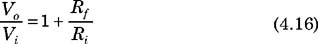
|
The conventional gain for...