4.8 DIFFERENTIATOR AND INTEGRATOR
The output of a differentiator, or differentiating amplifier, is the differentiated version of input given.
In an ideal op-amp, the voltage difference between the input terminals is zero. Since the voltage at the non-inverting input terminal is zero, the voltage at the inverting input terminal should also be zero.
| (4.38) | 
|
The currents entering the op-amp input terminals are zero.
| (4.39) | 
|
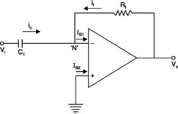 Figure 4.14: Basic differentiator.
 Writing Kirchhoff's Current Law at node ' N' yields
Substitute equation (4.39):
or
| (4.40) | 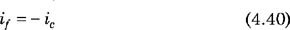
|
Write the current through the capacitor in terms of voltage:
Substitute equation (4.38):
| (4.41) | 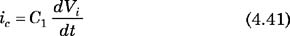
|
Write the current through the feedback resistor in terms of voltage:
Substitute equation (4.38):
Substitute equation (4.40):
Substitute equation (4.41):
| (4.42) | 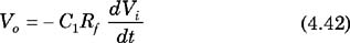
|
Equation (4.42) shows output voltage is proportional to derivative of input voltage
To have stability and to reduce noise, a resistor R 1 is placed in series with C 1 and a capacitor C f is placed in parallel with R f in a practical differentiator circuit.
The output of an integrator, or integrating amplifier, is the integrated version of the input.
The circuit for an integrator is the same as that of a differentiator, except the positions of the capacitor and resistor are switched.
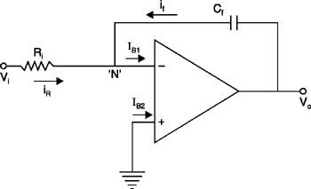 Figure 4.15: Basic integrator.
 In an ideal op-amp, the voltage difference between the input terminals is zero. Since the voltage at the non-inverting input terminal is zero, the voltage at the inverting input terminal is zero.
| (4.43) | 
|
The currents entering the op-amp input...