Programmed Review for Electrical Engineering, Third Edition

This text contains an organized review of the basic electrical engineering fundamentals, with 111 problems, solutions and explanations for the core electrical engineering concepts.
Discussions of and problems related to single-phase KVA and power factors, three-phase power factor and line current, phase sequence, unbalanced load, power factor correction, transmission line, transmission line regulation, and wattmeters.
This chapter covers single phase and polyphase power distribution and loads, power factor correction, transmission line calculations at power frequencies, and wattmeter measurements. Unless otherwise stated, the material in this chapter assumes all waveforms are 60 cycle sine waves. The vector, or phasor, diagram is used to aid in solution of problems.
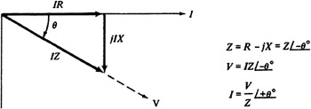
The phase angle is a very important parameter for properly locating different alternating quantities with respect to one another. If the applied voltage is v = V max sin ?t and it is known, from the nature and magnitude of the circuit parameters, that the current comes to a corresponding point on its wave before the voltage wave by ? degrees, the current can be expressed as i = I max sin ( ? t + ?). This is an example of a positive phase angle due to an RC circuit which produces leading current and a leading power factor, where the power factor is:
The phasor diagram for this example is as shown below:
For an RL circuit, the phasor diagram is as shown below:
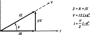
In this case, the current lags the voltage by ? degrees.
Power in ac circuits is either resistive ( real) or reactive.