Preface
The first generation of fiber-optic communication systems debuting in 1980 operated at a meager bit rate of 45 Mb/s and required signal regeneration every 10 km or so. However, by 1990 further advances in lightwave technology not only increased the bit rate to 10 Gb/s (by a factor of 200) but also allowed signal regeneration after 80 km or more. The pace of innovation in all fields of lightwave technology only quickened during the 1990s, as evident from the development and commercialization of erbium-doped fiber amplifiers, fiber Bragg gratings, and wavelength-division-multiplexed lightwave systems. By 2001, the capacity of commercial terrestrial systems exceeded 1.6 Tb/s. At the same time, the capacity of transoceanic lightwave systems installed worldwide exploded. A single transpacific system could transmit information at a bit rate of more than 1 Tb/s over a distance of 10,000 km without any signal regeneration. Such a tremendous improvement was possible only because of multiple advances in all areas of lightwave technology. Although commercial development slowed down during the economic downturn that began in 2001, it was showing some signs of recovery by the end of 2004, and lightwave technology itself has continued to grow. The primary objective of this two-volume book is to provide a comprehensive and up-to-date account of all major aspects of lightwave technology. The first volume, subtitled Components and Devices, is devoted to a multitude of silica- and semiconductor-based optical devices. The second volume, subtitled Telecommunication Systems, deals with the design of modern lightwave systems; the acronym LT1 is used to refer to the material in the first volume. The first two introductory chapters cover topics such as modulation formats and multiplexing techniques employed to form an optical bit stream. Chapters 3 through 5 consider the degradation of such an optical signal through loss, dispersion, and nonlinear effects during its transmission through optical fibers and how they affect the system performance. Chapters 6 through 8 focus on the management of the degradation caused by noise, dispersion, and fiber nonlinearity. Chapters 9 and 10 cover the engineering issues related to the design of WDM systems and optical networks. This text is intended to serve both as a textbook and a reference monograph. For this reason, the emphasis is on physical understanding, but engineering aspects are also discussed throughout the text. Each chapter also includes selected problems that can be assigned to students. The book's primary readership is likely to be graduate students, research scientists, and professional engineers working in fields related to lightwave technology. An attempt is made to include as much recent material as possible so that students are exposed to the recent advances in this exciting field. The reference section at the end of each chapter is more extensive than what is common for a typical textbook. The listing of recent research papers should be helpful to researchers using this book as a reference. At the same time, students can benefit from this feature if they are assigned problems requiring reading of the original research papers. This book may be useful in an upper-level graduate course devoted to optical communications. It can also be used in a two-semester course on optoelectronics or lightwave technology. A large number of persons have contributed to this book either directly or indirectly. It is impossible to mention all of them by name. I thank my graduate students and the students who took my course on optical communication systems and helped improve my class notes through their questions and comments. I am grateful to my colleagues at the Institute of Optics for numerous discussions and for providing a cordial and productive atmosphere. I thank, in particular, Renè Essiambre and Qiang Lin for reading several chapters and providing constructive feedback. Last, but not least, I thank my wife Anne and my daughters, Sipra, Caroline, and Claire, for their patience and encouragement. Govind P. Agrawal Rochester, NY |
 TABLE OF CONTENTS
Chapter 9.1.2 - Bandwidth and Capacity of WDM Systems
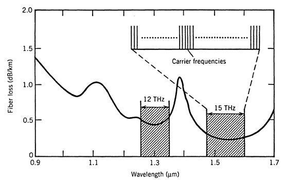
9.1.2 Bandwidth and Capacity of WDM SystemsWDM has the potential for exploiting the large bandwidth offered by optical fibers. Figure 9.2 shows the loss spectrum of a typical silica fiber and two low-loss transmission windows of optical fibers centered near 1.3 and 1.55 µm. Each of these spectral widows extends over more than 10 THz. If the so-called OH peak, resulting from residual water vapors trapped inside the core during manufacturing of silica fibers, can be eliminated using "dry" fibers, the entire spectral region extending from 1.25 to 1.65 µm can be exploited through WDM. The ultimate capacity of WDM systems can be estimated by assuming that the 300-nm wavelength range extending from 1,300 to 1,600 nm is employed for transmission using dry fibers. The minimum channel spacing can be as small as 50 GHz (or 0.4 nm) for 40-Gb/s channels. Since 750 channels can be accommodated over the 300-nm bandwidth, the resulting capacity can be as large as 30 Tb/s. If we assume that such a WDM signal can be transmitted over 1,000 km using optical amplifiers with dispersion management, the NBL product can exceed 30,000 (Tb/s)-km with the use of WDM technology. This should be contrasted with the third-generation commercial lightwave systems, which transmitted a single channel over 80 km or so at a bit rate of up to 10 Gb/s, resulting in NBL values of at most 0.8 (Tb/s)-km.
Figure 9.2: Typical loss spectrum of silica fibers and low-loss transmission windows (shaded regions) near 1.3 and 1.55 µm. The inset shows the basic idea behind WDM schematically.
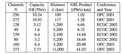
Experimental results on WDM systems can be divided into two groups based on whether the transmission distance is ~100 km or exceeds 1,000 km. Since the 1985 experiment in which ten 2-Gb/s channels were transmitted over 68 km [3], both the number of channels and the bit rate of individual channels have increased considerably. A capacity of 340 Gb/s was demonstrated in 1995 by transmitting 17 channels, each operating at 20 Gb/s, over 150 km [11]. This was followed within a year by several experiments that realized a capacity of 1 Tb/s. By 2001, the capacity of WDM systems exceeded 10 Tb/s in several laboratory experiments. In one experiment, 273 channels, spaced 0.4 nm apart and each operating at 40 Gb/s, were transmitted over 117 km using three in-line amplifiers, resulting in a total capacity of 11 Tb/s and a NBL product of 1.28 (Pb/s)-km [12]. Table 9.1 lists several WDM experiments in which the NBL product exceeded 1 Pb/s. In this table, OFC and ECOC stand, respectively, for the Optical Fiber Communication Conference and European Conference on Optical Communication, the two conferences where most record-breaking results are often presented. Table 9.1: High-capacity WDM transmission experiments
On the commercial side, WDM systems with a capacity of 40 Gb/s (16 channels at 2.5 Gb/s or 4 channels at 10 Gb/s) were available in 1996. The 16-channel system covered a wavelength range of about 12 nm in the 1.55-µm region with a channel spacing of 0.8 nm. WDM fiber links operating at 160 Gb/s (16 channels at 10 Gb/s) appeared in 1998. By 2001, WDM systems with a capacity of 1.6 Tb/s (realized by multiplexing 160 channels, each operating at 10 Gb/s) were available. This should be contrasted with the 10-Gb/s capacity of the third-generation systems available before the advent of the WDM technique. The use of WDM had improved by 2001 the capacity of commercial terrestrial systems by a factor of more than 6,000. Although systems with even higher capacities have been designed, they were not deployed commercially by 2004 because of the downturn in the telecommunication industry that began in 2001. |