Preface
The first generation of fiber-optic communication systems debuting in 1980 operated at a meager bit rate of 45 Mb/s and required signal regeneration every 10 km or so. However, by 1990 further advances in lightwave technology not only increased the bit rate to 10 Gb/s (by a factor of 200) but also allowed signal regeneration after 80 km or more. The pace of innovation in all fields of lightwave technology only quickened during the 1990s, as evident from the development and commercialization of erbium-doped fiber amplifiers, fiber Bragg gratings, and wavelength-division-multiplexed lightwave systems. By 2001, the capacity of commercial terrestrial systems exceeded 1.6 Tb/s. At the same time, the capacity of transoceanic lightwave systems installed worldwide exploded. A single transpacific system could transmit information at a bit rate of more than 1 Tb/s over a distance of 10,000 km without any signal regeneration. Such a tremendous improvement was possible only because of multiple advances in all areas of lightwave technology. Although commercial development slowed down during the economic downturn that began in 2001, it was showing some signs of recovery by the end of 2004, and lightwave technology itself has continued to grow. The primary objective of this two-volume book is to provide a comprehensive and up-to-date account of all major aspects of lightwave technology. The first volume, subtitled Components and Devices, is devoted to a multitude of silica- and semiconductor-based optical devices. The second volume, subtitled Telecommunication Systems, deals with the design of modern lightwave systems; the acronym LT1 is used to refer to the material in the first volume. The first two introductory chapters cover topics such as modulation formats and multiplexing techniques employed to form an optical bit stream. Chapters 3 through 5 consider the degradation of such an optical signal through loss, dispersion, and nonlinear effects during its transmission through optical fibers and how they affect the system performance. Chapters 6 through 8 focus on the management of the degradation caused by noise, dispersion, and fiber nonlinearity. Chapters 9 and 10 cover the engineering issues related to the design of WDM systems and optical networks. This text is intended to serve both as a textbook and a reference monograph. For this reason, the emphasis is on physical understanding, but engineering aspects are also discussed throughout the text. Each chapter also includes selected problems that can be assigned to students. The book's primary readership is likely to be graduate students, research scientists, and professional engineers working in fields related to lightwave technology. An attempt is made to include as much recent material as possible so that students are exposed to the recent advances in this exciting field. The reference section at the end of each chapter is more extensive than what is common for a typical textbook. The listing of recent research papers should be helpful to researchers using this book as a reference. At the same time, students can benefit from this feature if they are assigned problems requiring reading of the original research papers. This book may be useful in an upper-level graduate course devoted to optical communications. It can also be used in a two-semester course on optoelectronics or lightwave technology. A large number of persons have contributed to this book either directly or indirectly. It is impossible to mention all of them by name. I thank my graduate students and the students who took my course on optical communication systems and helped improve my class notes through their questions and comments. I am grateful to my colleagues at the Institute of Optics for numerous discussions and for providing a cordial and productive atmosphere. I thank, in particular, Renè Essiambre and Qiang Lin for reading several chapters and providing constructive feedback. Last, but not least, I thank my wife Anne and my daughters, Sipra, Caroline, and Claire, for their patience and encouragement. Govind P. Agrawal Rochester, NY |
Chapter 9.3.2 - Four-Wave Mixing
9.3.2 Four-Wave MixingFWM is considered the most dominant source of crosstalk in WDM systems, and its impact has been studied extensively [58]-[69]. As discussed in Section 4.3, FWM requires phase matching [39]. It becomes a major source of nonlinear crosstalk whenever the channel spacing and fiber dispersion are small enough to satisfy the phase-matching condition approximately [39]. This is the case when a dense WDM system operates close to the zero-dispersion wavelength of dispersion-shifted fibers with a channel spacing of 100 GHz or less. The physical origin of FWM-induced crosstalk, and the resulting system degradation, can be understood by noting that FWM generates a new wave at the frequency ωijk = ωi + ωj - ωk, whenever three waves at frequencies ωi, ωj, and ωk copropagate inside the fiber. For an N-channel system, i, j, and k can vary from 1 to N, resulting in a large combination of new frequencies generated by FWM. In the case of equally spaced channels, the new frequencies coincide with the existing frequencies, leading to coherent in-band crosstalk. When channels are not equally spaced, most FWM components fall in between the channels and lead to incoherent out-of-band crosstalk. In both cases, system performance is degraded because power transferred to each channel through FWM acts as a noise source, but the coherent crosstalk degrades system performance much more severely. A simple scheme for reducing the FWM-induced degradation consists of designing WDM systems with unequal channel spacings [41]. The main impact of FWM in this case is to reduce the channel power. This power depletion results in a power penalty that is relatively small compared with the case of equal channel spacings. Experimental measurements on WDM systems confirm the advantage of unequal channel spacings. In a 1999 experiment, this technique was used to transmit 22 channels, each operating at 10 Gb/s, over 320 km of dispersion-shifted fiber with 80-km amplifier spacing [64]. Channel spacings ranged from 125 to 275 GHz in the 1,532- to 1,562-nm wavelength region and were determined using a periodic allocation scheme [62]. The zero-dispersion wavelength of the fiber was close to 1,548 nm, resulting in near phase matching of many FWM components. Nonetheless, the system performed quite well with less than a 1.5-dB power penalty for all channels. The use of a nonuniform channel spacing is not always practical because many WDM components, such as optical filters and waveguide grating routers, require equal channel spacings. A practical solution is offered by the periodic dispersion-management technique discussed in Section 7.1. In this scheme, fibers with normal and anomalous GVD are combined to form a dispersion map such that GVD is high locally all along the fiber link even though its average value is quite low. Efficiency of the FWM process for a single type of fiber has been discussed in Section 4.3.1. The important question is how much this efficiency is reduced with the use of dispersion management. The calculation of FWM-induced crosstalk is quite complicated in general because it requires adding coherently the amplitudes of all FWM components that fall within the bandwidth of a specific channel. The FWM process is also sensitive to the states of polarization of the four channels involved. In a simple model, all channels are assumed to remain copolarized. One can then use the analysis of Section 4.3.1 and extend it to the case of dispersion-managed fiber links [59]-[68]. For a periodic dispersion map consisting of two types of fibers and amplifiers placed at the end of all fiber sections, the field generated at a frequency ωF = ωi + ωj - ωk through FWM is found by integrating Eq. (4.3.3) over all fiber sections. It depends on the channel powers and the map parameters as [61]
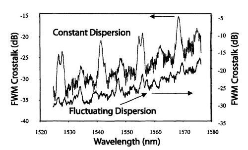
where δm = αm + iΔkm (m = 1,2), the integers j, k, and l can vary from 1 to N for an N-channel WDM system. The degeneracy factor df= 2 for j ≠ k and 1 otherwise, Δψ = Δk1L1 + Δk2L2 is the net phase shift after one map period, M is the number of map periods, and Δkm ≡ β2m(2πΔvch)2 (m = 1,2) represents the phase mismatch in the fiber section of length Ljwith loss αj, and dispersion β2j. In general, one must sum Bjkl over all combinations of j, k, and l that contribute to a given channel. Consider the power in one such term. If we sum over m in Eq. (9.3.12), we find that PF ≡ Bjkl2 is proportional to sin2(MΔψ/2)/ sin2(Δψ/2) and is enhanced by a factor of M2 whenever dispersion is fully compensated in each map period (Δψ = 0). A simple solution to eliminate such a resonant enhancement of FWM is to leave some residual dispersion after each map period and use postcompensation at the end of the fiber link. Even in that case FWM can be enhanced, if the dispersion slope is not compensated, for those channels for which Δψ = 2πm, where m is an integer. Such FWM resonances have been observed experimentally [63]. The crosstalk level for any channel is found by adding amplitudes Bjkl for all FWM components that fall within the channel bandwidth and comparing the resulting total power to the signal power in that channel. As an example, Figure 9.11 shows the FWM crosstalk calculated from Eq. (9.3.12) for a WDM system with 50-GHz channel spacing [68]. The dispersion map consists of seven spans of 70.5 km of dispersion-shifted fiber with D = -2.4 ps/(km-nm), followed with 70.5 km of standard fiber with D = 16.8 ps/(km-nm). The 1,128-km link consists of two such map periods. Multiple peaks seen in Figure 9.11 result from the FWM resonances. The peak heights are reduced significantly when the dispersion of each fiber section fluctuates around its average value with a standard deviation of 0.25 ps/(km-nm). Such fluctuations can occur for most practical fiber because of random variations in the core diameter of a fiber. The preceding analysis is too simple to model an actual WDM system accurately. In practice, all channels carry optical pulses in the form of pseudo-random bit patterns.
Figure 9.11: FWM crosstalk for a WDM system with 50-GHz channel spacing. FWM resonances are reduced considerably when the dispersion of each fiber section fluctuates around its average value. (After Ref. [68]; ©2002 IEEE.)
The random nature of the FWM crosstalk suggests that a statistical approach is more appropriate for estimating the impact of FWM on the performance of a WDM system. As early as 1994, it was suggested that this noise can be treated as being Gaussian in nature when the number of FWM terms contributing to a channel is large [59]. In a more realistic approach, the phase of each FWM term in Eq. (9.3.12) was assumed to be distributed uniformly in the 0 to 2π range, resulting in a bimodal distribution for the FWM noise [41]. In general, noise statistics depend on many factors [66]. The autocorrelation function of the FWM noise has also been calculated to show that different bit patterns in neighboring channels help to reduce the crosstalk level [69]. In summary, WDM systems designed with low-dispersion fibers suffer from FWM the most. The problem can be solved to a large extent with the use of dispersion management. Indeed, dispersion maps are used for all modern WDM systems for this reason. The FWM crosstalk is relatively small when the dispersion of each fiber section is large locally and FWM resonances are suppressed by matching the dispersion slope and avoiding full compensation over each map period. In fact, new kinds of fibers known as nonzero-dispersion-shifted fibers (NZDSFs) were designed and marketed after the advent of WDM systems. Typically, GVD is in the range of 4 to 8 ps/(km-nm) in such fibers to ensure that the FWM-induced crosstalk is minimized. FWM can still be a source of major concern in dense WDM systems in which each channel operates at 2.5 Gb/s, and the channel spacing is kept below 10 GHz [44].
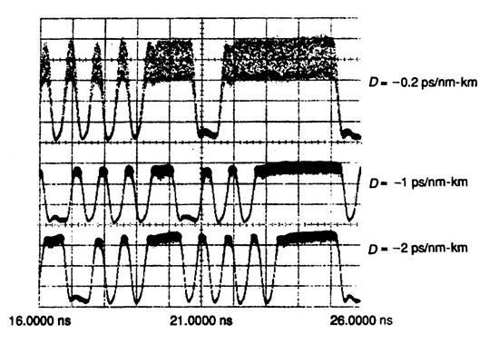
Figure 9.12: FWM-induced noise on the central channel at the output of a 25-km-long fiber when three 3-mW channels are launched with 1-nm spacing. (After Ref. [41]; ©1997 Elsevier.) |