Preface
The first generation of fiber-optic communication systems debuting in 1980 operated at a meager bit rate of 45 Mb/s and required signal regeneration every 10 km or so. However, by 1990 further advances in lightwave technology not only increased the bit rate to 10 Gb/s (by a factor of 200) but also allowed signal regeneration after 80 km or more. The pace of innovation in all fields of lightwave technology only quickened during the 1990s, as evident from the development and commercialization of erbium-doped fiber amplifiers, fiber Bragg gratings, and wavelength-division-multiplexed lightwave systems. By 2001, the capacity of commercial terrestrial systems exceeded 1.6 Tb/s. At the same time, the capacity of transoceanic lightwave systems installed worldwide exploded. A single transpacific system could transmit information at a bit rate of more than 1 Tb/s over a distance of 10,000 km without any signal regeneration. Such a tremendous improvement was possible only because of multiple advances in all areas of lightwave technology. Although commercial development slowed down during the economic downturn that began in 2001, it was showing some signs of recovery by the end of 2004, and lightwave technology itself has continued to grow. The primary objective of this two-volume book is to provide a comprehensive and up-to-date account of all major aspects of lightwave technology. The first volume, subtitled Components and Devices, is devoted to a multitude of silica- and semiconductor-based optical devices. The second volume, subtitled Telecommunication Systems, deals with the design of modern lightwave systems; the acronym LT1 is used to refer to the material in the first volume. The first two introductory chapters cover topics such as modulation formats and multiplexing techniques employed to form an optical bit stream. Chapters 3 through 5 consider the degradation of such an optical signal through loss, dispersion, and nonlinear effects during its transmission through optical fibers and how they affect the system performance. Chapters 6 through 8 focus on the management of the degradation caused by noise, dispersion, and fiber nonlinearity. Chapters 9 and 10 cover the engineering issues related to the design of WDM systems and optical networks. This text is intended to serve both as a textbook and a reference monograph. For this reason, the emphasis is on physical understanding, but engineering aspects are also discussed throughout the text. Each chapter also includes selected problems that can be assigned to students. The book's primary readership is likely to be graduate students, research scientists, and professional engineers working in fields related to lightwave technology. An attempt is made to include as much recent material as possible so that students are exposed to the recent advances in this exciting field. The reference section at the end of each chapter is more extensive than what is common for a typical textbook. The listing of recent research papers should be helpful to researchers using this book as a reference. At the same time, students can benefit from this feature if they are assigned problems requiring reading of the original research papers. This book may be useful in an upper-level graduate course devoted to optical communications. It can also be used in a two-semester course on optoelectronics or lightwave technology. A large number of persons have contributed to this book either directly or indirectly. It is impossible to mention all of them by name. I thank my graduate students and the students who took my course on optical communication systems and helped improve my class notes through their questions and comments. I am grateful to my colleagues at the Institute of Optics for numerous discussions and for providing a cordial and productive atmosphere. I thank, in particular, Renè Essiambre and Qiang Lin for reading several chapters and providing constructive feedback. Last, but not least, I thank my wife Anne and my daughters, Sipra, Caroline, and Claire, for their patience and encouragement. Govind P. Agrawal Rochester, NY |
Chapter 9.5.1 - Optimization of Dispersion Maps
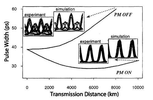
9.5.1 Optimization of Dispersion MapsAs discussed in Chapters 7 and 8, the performance of a single-channel lightwave system depends on details of the dispersion map (because of the nonlinear effects) and can be improved by optimizing the dispersion map. This is also the situation for WDM systems [97]-[106]. The parameters that can be adjusted are amount of precompensation, lengths and dispersions of each fiber section used to form the dispersion map, residual dispersion per map period, and the amount of postcompensation. It has been observed in many system experiments that the use of precompensation helps to improve the performance of long-haul systems [99]-[101]. In fact, such a scheme is known as the CRZ format because precompensation using a piece of fiber is equivalent to chirping optical pulses representing 1 bits in a bit stream. As discussed in Section 7.6.1, a phase modulator can also be used to prechirp optical pulses. The reason behind the improved system performance with prechirping is partly related to the results of Section 3.3.1 where it was shown that a chirped Gaussian pulse undergoes a compression phase when it is chirped suitably. Figure 9.17 shows how pulse width evolves with distance in one channel of a 16-chanel WDM system when a phase modulator is used to prechirp the pulses [99]. In this experiment, channels operated at 10 Gb/s with a channel spacing of 100 GHz and a periodic dispersion map was employed with a small amount of residual anomalous dispersion per map period. As expected, the pulse width increases monotonically in the absence of phase modulation (PM) but is smaller than its input value even after 10,000 km when PM is employed to prechirp the pulse. The measured and simulated eye diagrams show clearly the improvement realized with the use of PM.
Figure 9.17: Evolution of pulse width along the link length in one channel of a 16-channel WDM system. Insets show the experimentally measured and numerically simulated eye diagrams at a distance marked by arrows. (After Ref. [99]; ©2000 IEEE.)
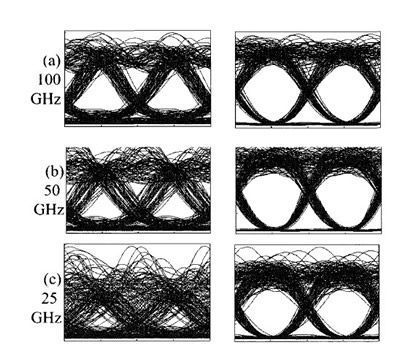
An attractive scheme that is capable of cancelling the XPM-induced distortion for an arbitrary dispersion map makes use of midspan spectral inversion through optical phase conjugation [107]. The basic idea behind such a scheme has been discussed in Section 7.5 in the context of single-channel systems. The same scheme can also eliminate interchannel nonlinear effects. The reason can be understood by noting that the sign of dispersion parameters for all fiber sections is effectively inverted after the phase conjugator. When a phase conjugator is placed in the middle of the entire link, the dispersion map appears symmetric, and XPM effects nearly vanish. Another way to understand this process is to note that all XPM-induced frequency shifts introduced in the first half of the fiber link change sign and are cancelled in the second half. Figure 9.18 compares the numerically simulated eye patterns at a distance of 2,560 km for three channel spacings. Each NRZ-format channel of the 5-channel WDM system operates at 10 Gb/s and is launched with 1 mW of average power. Amplifiers are spaced 80 km apart. Each 80-km fiber section is made of standard fiber with D = 16 ps/(km-nm) and γ = 1.2 W-1/km and its dispersion is fully compensated using DCFs. When a spectral inverter is placed after 16 spans at a distance of 1,280 km, the eye pattern is improved drastically because of the near cancellation of XPM-induced timing jitter. The predicted improvement in the Q factor exceeds 5 dB. A simple approach to XPM suppression consists of introducing relative time delays among the WDM channels after each map period such that pulses in neighboring channels are unlikely to overlap most of the time [79]. The use of a RZ format is quite helpful in this context because pulses occupy only a fraction of the bit slot. In a 10-channel WDM experiment, time delays were introduced by using 10 fiber gratings spaced apart by varying distances chosen to enhance XPM suppression [81]. The BER floor observed after 500 km of transmission disappeared after the XPM suppressors (consisting of 10 Bragg gratings) were inserted every 100 km. The residual power penalty at a BER of 10-10 was below 2 dB for all channels.
Figure 9.18: Numerically simulated eye patterns at a distance of 2,560 km for a channel spacing of (a) 100, (b) 50, and (c) 25 GHz obtained without (left column) and with (right column) a midspan spectral inverter. (After Ref. [107]; ©2004 IEEE.)
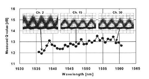
Similar to the case of single-channel systems, sliding-frequency filters can reduce timing jitter in WDM soliton systems [108]. In practice, Fabry-Perot filters are used because their periodic transmission windows allow filtering of all channels simultaneously. For the best operation, mirror reflectivities are kept low (below 25%) to reduce the finesse. Such low-contrast filters remove less energy from pulses but are as effective as filters with higher contrast. The physical mechanism remains the same as for single-channel systems. More specifically, collision-induced frequency shifts are reduced because the filter forces the soliton frequency to move toward its transmission peak. Filtering can also relax the condition Lcoll > 2LA, allowing Lcoll to approach LA. The technique of synchronous modulation can also be applied to WDM systems for controlling the XPM-induced timing jitter. As discussed in Section 8.3.3, the performance of a single-channel soliton system can be improved by using a dense dispersion map for which the map period Lmap is a fraction of the amplifier spacing such that LA= mLmap, where m is an integer. The same conclusion should hold for CRZ systems. Indeed, in a 2002 experiment in which 32 channels, each operating at 40 Gb/s, were transmitted over a distance of 3000 km, it was observed that system performance improved for m = 2 with LA = 50 km [104]. Two fibers used to form the periodic map had dispersion of 20 and -63 ps/(km-nm). The launch power was optimized to maximize the Q factor at the receiver. Figure 9.19 shows the measured Q factors for all channels together with the eye patterns for 3 channels. Even the lowest value of 11.9 dB is large enough that this system can operate with a BER below 10-9 after forward error correction. Interestingly, it was observed in this experiment that the performance of the WDM system became worse for m = 4, even though this choice improved performance when only a single-channel was transmitted. We can thus conclude that the interchannel XPM effects are enhanced when the map period becomes too small. This behavior can be understood by noting that when the map period becomes smaller than the collision length, dispersion changes sign on such a short length scale, and the relative motion of two colliding pulses follows such a zigzag path, that the XPM-induced timing jitter is likely to be enhanced.
Figure 9.19: Measured Q factors after 3,000 km for 32 channels spaced 100 GHz apart. Insets show the eye patterns for three channels marked by arrows. (After Ref. [104]; ©2002 IEEE.)
The pseudo-linear approach is most suitable for WDM systems in which the bit rate of each channel is relatively large (40 Gb/s or more) and RZ-format pulses shorter than 10 ps are employed. In one 1999 experiment, two 40-Gb/s channels were transmitted over 800 km of standard fiber using 2.5-ps pulses [109]. In this experiment, the entire dispersion accumulated over 800 km was compensated at the receiver end. However, the interchannel XPM effects played a relatively minor role since the channels were separated by 400 GHz, a relatively large channel spacing. In another 1999 experiment, four 40-Gb/s channels were transmitted with 250-GHz spacing using 4-ps pulses. Several other experiments have employed the pseudo-linear design for transmitting multiple 160-Gb/s channels. In a 3-Tb/s WDM experiment, 19 channels, each operating at 160 Gb/s, were transmitted over 40 km with 480-GHz spacing among channels [111]. In a 2001 experiment, several 160-Gb/s channels were transmitted over 400 km using a channel spacing of only 300 GHz [112]. More recently, four 160-Gb/s were transmitted over 225 km with 75-km amplifier spacing. The channel spacing was 400 GHz in this experiment, and the measured Q2 values for all four channels were close to 15 dB. |