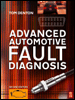
Advanced Automotive Fault Diagnosis, Second Edition
Chapter 4: Oscilloscope Diagnostics

4.1 Introduction

This chapter outlines the methods used and the results of using an oscilloscope to test a variety of systems. It will be a useful reference as all the waveforms shown are from a correctly operating system. The chapter is split into three main sections: sensors, actuators and ignition.

Author's Note

The waveforms in this chapter were captured using the PicoScope automotive oscilloscope. I am most grateful to the PicoTech team for supplying information and equipment to assist in the production of this chapter (http://www.picoscope.com).

4.2 Sensors

4.2.1 ABS speed sensor waveform

The anti-lock braking system (ABS) wheel speed sensors have become increasingly smaller and more efficient in the course of time (Figure 4.1). Recent models not only measure the speed and direction of wheel rotation but can be integrated into the wheel bearing as well.


Figure 4.1: ABS wheel speed sensors ( Source: Bosch Press)

The ABS relies upon information coming in from the sensors to determine what action should be taken. If, under heavy braking, the ABS electronic control unit (ECU) loses a signal from one of the road wheels, it assumes that the wheel has locked and releases that brake momentarily until it sees the signal return. It is therefore imperative that the sensors are capable of providing a signal to the ABS ECU. If the signal produced from one wheel sensor is at a lower frequency than the others the ECU may also react.

The operation of an ABS sensor is similar to that...

UNLIMITED FREE
ACCESS
TO THE WORLD'S BEST IDEAS

SUBMIT
Already a GlobalSpec user? Log in.

This is embarrasing...

An error occurred while processing the form. Please try again in a few minutes.

Customize Your GlobalSpec Experience

Category: Variable Reluctance Linear Position Sensors and Switches
Finish!
Privacy Policy

This is embarrasing...

An error occurred while processing the form. Please try again in a few minutes.