Composite Structures, Design, Safety and Innovation
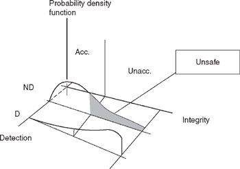
2.3: EXPLICIT DESIGN CONSTRAINTS

2.3 EXPLICIT DESIGN CONSTRAINTS

In order to establish design constraints, we have to return to the definition of an

"Unsafe State" of a PSE. The basic definition is described in Figure 2.7.


Figure 2.7: Unsafe state.

2.3.1 Damage Tolerance Constraint

Figure 2.7 shows a "detected" branch, D, and a "non-detected," branch ND, and the "integrity" axis shows the level of integrity in these two zones, one acceptable and the other unacceptable. The "Unsafe," shaded area, represents an "Unacceptable level of integrity that is undetected." The design objective is to keep the probability of being in the "unsafe zone" small, which could be expressed as:


Here, time T represents a major inspection and time ? the previous major inspection. The probability of damage undetected in two consecutive major inspections with unacceptable level of integrity at the second, p can be translated to structural design criteria once p r is set.

The previous section demonstrated the importance of damage tolerance integrity, which leads to a "tie-in" with structural properties, and can be expressed as:


where the sub-events are:

  • B T: Residual strength, RS is larger than Limit Load Requirement, LLR; RS > LLR;

  • D T: Damage size, D s is smaller than Maximum Allowed Damage, MAD; D s < MAD;

  • X T: Damage is present;

and in general Y is the complement to Y.

The first term on the right-hand side of Eq. (2.7) represents the probability that the residual strength...

UNLIMITED FREE
ACCESS
TO THE WORLD'S BEST IDEAS

SUBMIT
Already a GlobalSpec user? Log in.

This is embarrasing...

An error occurred while processing the form. Please try again in a few minutes.

Customize Your GlobalSpec Experience

Category: Battery Monitors and Testers
Finish!
Privacy Policy

This is embarrasing...

An error occurred while processing the form. Please try again in a few minutes.