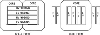
Power Electronics Design: A Practitioner's Guide

Two basic core and coil arrangements, shell form and core form, are used in transformers. Both are illustrated in Fig. 7.6 in single-phase versions. The shell form is appropriate for the largest and highest- voltage transformers. The windings are pancake coils that are stacked prior to assembly of the core. The coils are surrounded by core material except for the end turns, and they can be braced for high fault currents and interleaved for low leakage reactance. Shell form transformers are almost invariably oil filled, and units as large as 500 MVA have been built for generator transformers.
The core form design places the coils over a vertical leg of laminations. The coils, in effect, surround the core. Coils are lathe wound with either circular or rectangular cross sections. This construction is appropriate for smaller transformers and to dry-type units. Core form construction in the 10 kVA to 20 MVA range is quite common. One fact that makes core form designs difficult in very large units is bracing for fault currents. Since force is proportional to the square of the current, a fault current of 20 times normal creates 400 times normal stresses. The coils are subject to large radial forces, and they have no bracing except for the circumferential coil wrapper. The inner winding tends to be compressed against the core on faults, while the outer winding heads for outer space. The core, or at least the core corners, may be covered...