Elements of Propulsion: Gas Turbines and Rockets
With worked examples, numerous homework problems, illustrations and pictures, this book provides a complete introduction to gas turbine and rocket propulsion for aerospace and mechanical engineers.
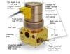
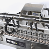
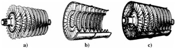
The axial-flow compressor is one of the most common compressor types in use today. It finds its major application in large gas turbine engines like those that power today's jet aircraft. A cutaway view of an axial-flow compressor is shown in Fig. 9.2. The compressor is made up of two major assemblies: the rotor with its blades, as shown in Fig. 9.2a, and the casing with its stationary blades (called stators), as shown in Fig. 9.2b.
This chapter investigates the relationships of the desired performance parameters to the related blade loading and resultant fluid flow angles. Because the flow is inherently three-dimensional, the problem of analysis seems almost incomprehensible. Do not fear! This most complex flow can be understood by dividing the three-dimensional flowfield into three two-dimensional flowfields. The complete flowfield will be the "sum" of these less complex two-dimensional flows. The two-dimensional flowfields are normally called the throughflow field, the cascade field (or blade-to-blade field), and the secondary flowfield. Each of these fields is described in more detail next.
The throughflow field is concerned with the variation in fluid properties in only the radial r and axial z directions (see Fig. 9.3). No variations in the ? direction occur. A row of blades is modeled as a thin disk that affects the flowfield uniformly...