Elements of Propulsion: Gas Turbines and Rockets

With worked examples, numerous homework problems, illustrations and pictures, this book provides a complete introduction to gas turbine and rocket propulsion for aerospace and mechanical engineers.
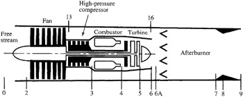
We consider the turbofan engine in which the core flow and bypass flow are mixed together before passing through an afterburner and nozzle. Figure SM5.1 shows a view of such a turbofan engine, and Fig. SM5.2 shows the ideal engine cycle on a T-s diagram. Modern fighter aircraft use this type of engine because it gives the required high specific thrust with the afterburner on and lower thrust specific fuel consumption than the turbojet engine when the afterburner is off. Since this engine has a single inlet and exhaust, the ideal thrust of this engine is given by
| (SM5.1) | 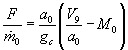 |

The analysis of this engine requires the definition of the total temperature and total pressure ratios across the mixer. We define
| (SM5.2) | |
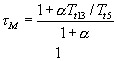
The flow in the bypass duct from station 13 to 16 is considered to be reversible and adiabatic. The bypass stream enters the mixer at station 16 with the same total properties as the fan discharge. An energy balance of the mixer gives
or
Since T t 6 = T t 5, then
This equation can be written in terms of the engine ?'s and bypass ratio ? as
| (SM5.3) | 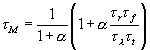 |
Fluid dynamics requires equal static pressures at stations 6 and 16. Normal design of the mixer has the Mach numbers of the two entering streams nearly equal. For...