Advanced Hypersonic Test Facilities
This book presents a number of new, innovative approaches to satisfy the enthalpy requirements for air-breathing hypersonic vehicles and planetary entry problems.
The development of the UTA high-performance shock tube followed suggestions by Bakos and Erdos35 that high-enthalpy flows could be generated using a detonation driver quickly and inexpensively. A shock tunnel was modified for this purpose. The shock tube consists of a high-pressure tube, a detonation tube, a driven tube, and a test section in the form of an electrical conductivity channel as shown schematically in Fig. 48a. The driver tube was filled with either air or helium and was used to induce a detonation wave in the detonation tube. The basic principle of this approach, dubbed the shock-induced detonation technique, is a multi-step wave driver process, for example, as implemented in expansion tubes and a variant of the double-detonation driver technique as described above, which can achieve high-enthalpy flows. A secondary benefit is that the flow from the driver section could sustain the C-J detonation pressure, the so-called perfectly driven mode. Air or helium were used to fill the driver section. A simplified wave diagram for operation as a reflected shock tunnel is shown in Fig. 48b.
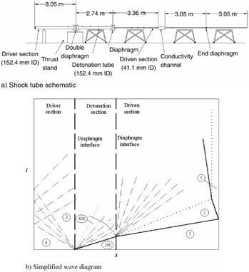
The driver tube has a bore of 152.4 mm and a length of 3 m. The detonation tube also has a bore of 152.4 mm, but is 2.74 m long. Both tube sections are rated for a pressure of 41.3 MPa. These two tubes are...