Complete Wireless Design

If you want to climb the learning curve with grace, and start designing what you need immediately, this easy-to-understand guide will help you design an entire radio system from the ground up.
 TABLE OF CONTENTS
 Single-ended amplifier configurations cannot always supply us with all of the power we may need for certain applications, for we may require up to several hundred watts of output power. This can be accomplished with RF parallel amplifiers (Fig. 3.104).

With parallel amplifiers, each transistor is on or off at the same time, unlike push-pull, which sequentially distributes the power back and forth for equal, but alternating, time periods.
Since the output current of the parallel circuit is shared evenly between the transistors (when perfectly matched), this will double the power handling capabilities ( P = IE) compared to a single-ended amplifier configuration. Parallel amplifiers allow the entire parallel circuit to function as if it were a single high-power transistor, at any bias desired (Class A, AB, B, and C). Figure 3.105 demonstrates a complete parallel circuit, with impedance matching, biasing, and filtering. Parallel amplifier circuits must have excellently matched active devices, and their input and output capacitances will also be double that of a single device which can be problematic with high-frequency operation.
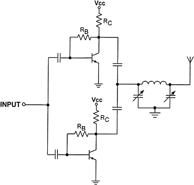
Gain will stay the same whether a single power amplifier or a parallel power amplifier configuration is used. The advantage of paralleling amplifiers is that the output power capability (P1dB) will increase by 3 dB for two amplifiers (Fig. 3.106), and by 6 dB for four...