Frequency-Domain Characterization of Power Distribution Networks
As several illustrations in this section will show, the actual parameters of a bypass capacitor (capacitance, resistance, and inductance) all may depend not only on the internal geometry of the capacitor, but also on the geometry of user application. The most difficult and most controversial of these parameters is the parameter defined as the inductance of bypass capacitor. It is commonly called the effective series inductance (ESL). First, we look at some of the possible definitions of ESL, followed by examples of resistance and inductance manipulated by various internal and external connection geometries.
The ESL of a part has several possible definitions. Inductance in real circuits is always realized by current loops. While the concept of partial self- and mutual inductances allows us to break down the loop inductance into components, measuring these inductance components directly and separately is not easy. In all of the examples in this book, unless otherwise noted, the measured or extracted inductance refers to some type of loop inductance.
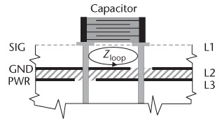
For PDN design and validation, however, the loop inductance may not be the most convenient parameter to characterize the high-frequency behavior of a bypass capacitor. This will be explained using Figure 8.9.
The figure shows one bypass capacitor connected to a pair of planes through vias. The full construction creates a Z loop