Introduction to RF Stealth

Providing a new generation of designers with a firm and proven basis for new developments, this book presents and explains first order methods for the design of active and passive stealth properties.
 TABLE OF CONTENTS
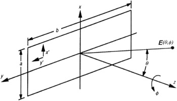
 Most stealth data link and radar antennas require high gain and low sidelobes and thus are arrays of radiators, not single elements. For example, consider the rectangular aperture and coordinate system given in Fig. 6.4 and repeated in Fig. 6.13. Recall that this aperture was first introduced in Chapter 2, Fig. 2.21, without explanation to calculate "cookie cutter" footprints. Define the height of the aperture in the x dimension as a, and the width of the aperture in the y dimension as b; the angle ? is measured from the z axis, and the angle ? is measured from the xz plane about the z axis. Then, integrating Equation (6.12) with uniform weighting in the x' and y' directions and calculating the equivalent power normalized over 4 ? steradians will yield the far-field gain. The normalized far-field gain pattern for uniform aperture E-field in the x direction is given in Equations (6.26).

or more commonly,

where

Often, the cos( ?) factor in Equation (6.26a) is dropped for pattern plots within 30 of the normal, because other edge effects make the pattern prediction poor at large off angles. In addition, if a purely scalar diffraction assumption (TEM) is made, then the raised cosine factor does not appear in the gain equation or corresponding electric fields for the rectangular aperture. Parallelogram apertures easily...