Learning Mastercam Mill X Step by Step in 2D

Presenting the contents in a clear and logical sequence without wordy explanations, this unique text presents a thorough introduction to Mastercam Mill X for students with little or no prior experience.
 TABLE OF CONTENTS
 After completing this chapter you will be able to:
Know the various methods of chaining 2D entities for contour machining
State the common problems in 2D chaining and the methods of correction.
Understand the meaning of the parameters in the Contour(2D) dialog box.
Know how to specify the chaining, tooling and contouring parameters required to contour machine a sample part.
Understand the meaning of the parameters in the Pocket(Standard) dialog .box.
Know how to specify the chaining, tooling and pocketing parameters required to machine a pocket in a part.
On the CD A set of points, lines, arcs and splines chained together into a single curve is called a machining contour. When Mastercam is directed to contour a part it does so by moving the cutting tool along the chain.
The various methods of creating a contour are described below.

The operator clicks the chain start point on an entity. Chaining will proceed from the start point in the direction toward the midpoint of the entity. All entities connected end to end will be included in the chain. The point at the end of the last entity in the chain is the endpoint. For closed chains the start and endpoints coincide.
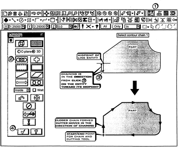
Click  the Contour Toolpaths button
Click  on the chain button
Select contour chain 1
Click