Figure 13.1(a) shows an electric motor with a flange mount, and Fig. 13.1(b) shows a typical application, a vertical motor/pump combination. The alignment of flange-mounted equipment is slightly different from machines with four feet. The same instruments and methods can be used to measure the shaft orientations, either reverse-indicator or face-and-rim. The face-and-rim method is the preferred method in this situation because the calculations are easier for angularity from the face readings. Because of the absence of four feet, it is not possible to correct for angularity and offset with a single move, which is the shining feature of the reverse-indicator method. The angularity must be corrected first by shimming under the flange bolts. The information to calculate the shimming comes solely from the face readings. The offset can then be corrected by sliding the unit parallel to the flange. The information for offset correction is obtained solely from the rim reading. Either method, reverse-indicator or face-and-rim, can be used to measure shaft orientations and judge acceptability. However, reverse-indicator readings need to be converted to an offset and a separate angularity correction. The tolerances for acceptability are the same as any other machine with a single coupling, as outlined in Chapter 9, "Alignment Tolerances."
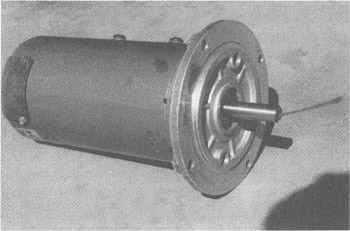 Figure 13.1a: Flange-mount motor.
 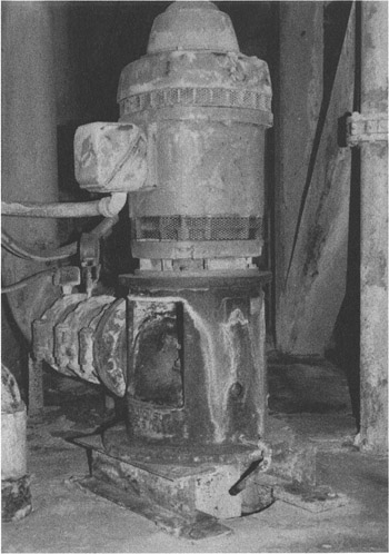 Figure 13.1b: Vertical motor/pump.
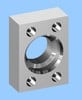
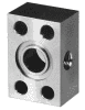
 The major problem with flange-mounted equipment is making offset corrections with rabbet joints. Figure 13.2 illustrates a rabbet joint (also called a "boss fit") for a vertical motor. The rabbet joint is merely a locating feature. It has...
Copyright The McGraw-Hill Companies, Inc. 2000 under license agreement with Books24x7