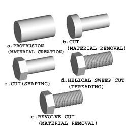
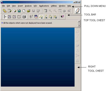
Pro/ENGINEER ReferencePoint Suite

Point 4: Basic Part Modeling Techniques

Veeramani M.

Pro/Engineer (Pro/E) is used to convert conceptual ideas about objects into 3-Dimensional (3-D) part models. Using Pro/E, you can perform various operations such as adding or removing material to and from the objects to create a part model. Pro/E records the operations in the form of features.

This ReferencePoint discusses the basics of part modeling. It describes various features that can be created, and the tools that are used to manipulate the features. In addition, it describes how to create datum features that are used as references to create other features, and explains the use of datum features in modeling.

Basics of Part Modeling

You need to create a part object to create a solid model. You create a part object by creating features using various tools in Pro/E. For example, to manufacture a hexagonal screw:

  1. Cut a steel bar or rod of the required diameter and size.

  2. Create threads.

  3. Shape the head into a hexagon.

  4. Turn the head and remove the sharp edges.

You can replicate the steps in Pro/E and create a solid model, as shown in Figure 2-4-1:


Figure 2-4-1: Creating a Hexagonal Screw in Pro/E

Creating a Part Object

Use Pro/E to create a part object. Start the Pro/E application, and the Pro/E Base window appears, as shown in Figure 2-4-2:


Figure 2-4-2: The Pro/E Base Window

Use the pull-down menu options to create features, customize the screen, and configure the Pro/E session. Use icons in the toolbar to manipulate the model. You can...

UNLIMITED FREE
ACCESS
TO THE WORLD'S BEST IDEAS

SUBMIT
Already a GlobalSpec user? Log in.

This is embarrasing...

An error occurred while processing the form. Please try again in a few minutes.

Customize Your GlobalSpec Experience

Category: Computer-Aided Design (CAD) Services
Finish!
Privacy Policy

This is embarrasing...

An error occurred while processing the form. Please try again in a few minutes.