RF Power Amplifiers
In this comprehensive reference, the author presents a full account of RF amplifiers and shows that understanding large-signal RF circuits is simply a matter of understanding the basic principles and their applications.
For Class A operation [1-8], the quiescent point ( I dc) must be selected to keep the transistor in its active region during the entire RF cycle, thus assuring a 360 degree conduction angle.
A simplified analysis of the single-ended Class A amplifier is based on the following assumptions:
The RF choke is ideal. It has no series resistance, and its reactance at the operating frequency is infinite. Consequently, the RF choke allows only a constant (DC) input current, I dc, whose value is determined by the bias circuit (not shown in Figure 2-1).
C d is a DC-blocking capacitor (short circuit at the operating frequency).
The active device behaves as an ideal controlled-current source. For this simplified analysis, disregard the saturation voltage and/or the saturation resistance of the transistor. The transfer characteristic of the active device is assumed to be perfectly linear, i.e., a sinusoidal drive signal determines a sinusoidal collector current.
Based on these assumptions, the collector current is given by
where q = w t = 2 p ft is the angular time. The output current is sinusoidal.
The collector voltage is
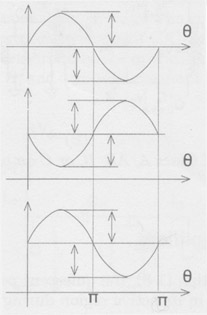
The corresponding waveforms of the Class A single-ended circuit are shown in Figure 2-3. Class A operation is assured by maintaining i( q ) ? 0 and v( q ) ? 0. Therefore, the transistor remains in the active region if the following...