RF Power Amplifiers
In this comprehensive reference, the author presents a full account of RF amplifiers and shows that understanding large-signal RF circuits is simply a matter of understanding the basic principles and their applications.
Most designers are familiar with the basic principles of the conventional (wire-wound) transformer. Although it seems the best option for broadband impedance matching, the conventional transformer is almost useless in RF power amplifiers. This section briefly discusses the basic limitations of the conventional transformer, then looks at the most popular circuit for broadband impedance matching in RF PAs the transmission-line transformer.
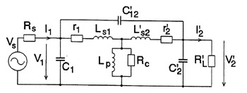
The conventional transformer consists of two coils (see Figure 2-71) placed so a magnetic field in one coil links the other coil, mostly via a magnetic core [4, 5, 37, 38].
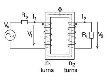
The voltages induced in the primary and secondary coils are proportional to the number of turns in that coil; the currents through the coils are inversely proportional to the number of turns. For an ideal transformer (that is, a transformer with perfect magnetic coupling and no loss of energy), the resistance seen across the primary winding (see Figure 2-72) is given by
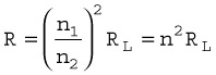
where

is the turns ratio.
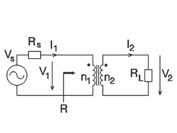
Because the number of turns in both primary and secondary coils may be arbitrary, the conventional transformer may be used to assure a broadband matching of any impedance value. However, the use of a conventional transformer for broadband impedance matching raises difficulties due to its frequency limitations.