RF Power Amplifiers
In this comprehensive reference, the author presents a full account of RF amplifiers and shows that understanding large-signal RF circuits is simply a matter of understanding the basic principles and their applications.
This section concentrates on the push-pull circuit of Figure 2-2 [1-10]. because it is the circuit most used in Class B and AB amplifiers. The major results for a single-ended Class B or AB amplifier are listed in section Current-Source Class C Amplifiers.
A push-pull Class B RF PA operates much like a Class B audio frequency PA. The two active devices ( Q 1 and Q 2) are driven 180 degrees out-of-phase so they are alternately active (i.e., behave as controlled-current sources) and cut off for each half of the RF cycle (see Figure 2-5).

A simplified analysis of the Class B circuit is based on the usual assumptions about the ideal behavior of components given in the previous section. Moreover, the output transformer T 2 is ideal, having m turns in each half of the primary winding and n turns in the secondary winding. In each half-cycle, a half-sinusoidal current of peak value I is carried through one-half of the primary winding of T 2. As a result, the secondary current is sinusoidal
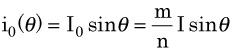
and determines a sinusoidal output voltage
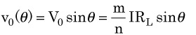
The voltages across the two transistors are given by
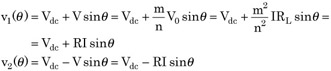
where
is the resistance seen across one-half of the primary winding with the other half open (i.e., the equivalent load resistance of each transistor). The two transistors do not saturate if V