RF Power Amplifiers
In this comprehensive reference, the author presents a full account of RF amplifiers and shows that understanding large-signal RF circuits is simply a matter of understanding the basic principles and their applications.
A Class D amplifier is a switching-mode amplifier that uses two active devices driven in a way that they are alternately switched ON and OFF. The active devices form a two-pole switch that defines either a rectangular voltage or rectangular current waveform at the input of a tuned circuit that includes the load. The load circuit contains a band- or low-pass filter that removes the harmonics of the rectangular waveform and results in a sinusoidal output.
In its simpler form, the load circuit can be a series or parallel resonant circuit tuned to the switching frequency; such a load circuit will be considered here. In practical applications, this circuit can be replaced by narrowband pi- or T-matching circuits, or by band- or low-pass filters (in wideband amplifiers).
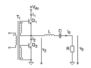
The CVS circuit is presented in Figure 3-1(a) [1-11]. Input transformer T 1 applies the drive signal to the bases of Q 1 and Q 2 in opposite polarities. If the drive is sufficient for the transistors to act as switches, Q 1 and Q 2 switch alternately between cut-off (OFF state) and saturation (ON state). The transistor pair forms a two-pole switch that connects the series-tuned circuit alternately to ground and V dc.
The analysis below is based on the following assumptions:
The series resonant circuit, tuned to the...