RF System Design of Transceivers for Wireless Communications
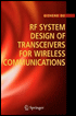
Addressing specifications that are critical for the design process, this book develops systematic methods for RF systems design, complete with a comprehensive set of design formulas.
 TABLE OF CONTENTS
 The I and Q signal imbalances limit the image rejection and the dynamic range of a receiver or a transmitter. The image-rejection formula (3.3.4) can derived based a simplified quadrature conversion system model as shown in Fig. 3C.1. The received RF desired signal has a frequency ? RF an angle modulation ?( t) and an amplitude of normalized to one. Assuming that all the imbalances in the I and Q channels are concentrated on the imbalances of the quadrature LO signals, the amplitude normalized I and Q LO signals are expressed as cos( ? LOt) and (1 + ?) sin( ? RFt + ?) , respectively, where ? is the amplitude imbalance and ? is the phase imbalance.
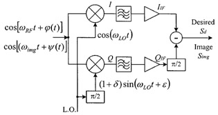
If the gain of the converter is unity, the I and Q signals at the downconverter outputs have expressions as

and
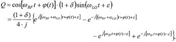
where ? IF is the low IF frequency.
After low-pass filtering, if not considering the channel gain or loss, we obtain two low IF signals having forms,
| (3C.1) |  |
and
| (3C.2) |  |
The desired low IF signal S d can be obtained from the I IF signal subtracting 90 phase shifted Q IF signal. It is expressed as
| (3C.3) | 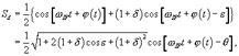 |
where
| (3C.4) |  |
For the image signal it possesses a frequency ? img = ? RF - 2 ?