Linear Circuit Design Handbook

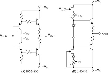
In the early days of high speed circuits, simple emitter followers were often used as high speed buffers. The term buffer was generally accepted to mean a unity-gain, open-loop amplifier. With the availability of matching PNP transistors, a simple emitter follower can be improved, as shown in Figure 2-1(A). This complementary circuit offers first-order cancellation of DC offset voltage, and can achieve bandwidths greater than 100 MHz. Typical offset voltages without trimming are usually less than 50 mV, even with unmatched discrete transistors.
If high input impedance is required, a dual FET can be used as an input stage ahead of a complementary emitter follower, as shown in Figure 2-1(B). This form of the buffer circuit was implemented by both National Semiconductor Corporation as the LH0033, and by Analog Devices as the ADLH0033.
Circuits such as these achieved bandwidths of about 100 MHz at fairly respectable levels of harmonic distortion, typically better than ?60dBc. However, they suffered from DC and AC nonlinearities when driving loads less than 500 ?.
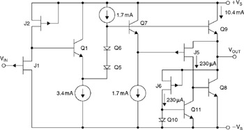
One of the first totally monolithic implementations of these functions was the Precision Monolithics, Inc. BUF03 shown in Figure 2-2 (see Reference 1). PMI is now a division of Analog Devices. This open-loop IC buffer achieved a bandwidth of about 50 MHz for a 2V peak-to-peak signal.
The BUF03 circuit is interesting because...