Linear Circuit Design Handbook

In most cases, the digital signals of a converter are designed to operate at standard levels with standard interface specifications. Common interfaces are parallel or serial (most commonly SPI or I 2C compatible, but, at the high speed, LVDS is making inroads). The fact that we are compatible with defined standards means that the timing and voltage levels defined in these specifications are met.
The digital signals of a converter are generally divided into one of three groups: address, data, and control.
Common timing specifications include:
Logic Low Level: The voltage level at which the signal is guaranteed to be seen as a logic 0. This level is generally specified at whatever power supply the converter is guaranteed to run at. This means that you will generally see different specification tables for 3V and 5V supplies.
Logic High Level: The voltage level at which the signal is guaranteed to be seen as a logic 1. Again, this will be given at the various power supply voltages.
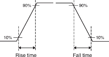
Rise Time: For a step function, the time required for a signal to change from a specified low value to a specified high value. Typically, these values are 10% and 90% of the step height (see Figure 6-176).
Figure 6-176: Rise time and fall time
Fall Time: For a step function, the time required for a signal to change from a specified high value to a specified low value. Typically, these values are 10% and...