Linear Circuit Design Handbook

Section 6-3: Sigma delta Converters

Section 6-3: Sigma delta Converters

Historical Perspective

The sigma delta ( ?- ?) ADC architecture had its origins in the early development phases of PCM systems specifically, those related to transmission techniques called delta modulation and differential PCM. (An excellent discussion of both the history and concepts of the sigma delta ADC can be found by Max Hauser in Reference 1).

The driving force behind delta modulation and differential PCM was to achieve higher transmission efficiency by transmitting the changes (delta) in value between consecutive samples rather than the actual samples themselves.

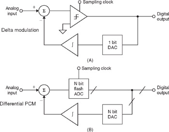
In delta modulation, the analog signal is quantized by a 1-bit ADC (a comparator) as shown in Figure 6-85(A). The comparator output is converted back to an analog signal with a 1-bit DAC, and subtracted from the input after passing through an integrator. The shape of the analog signal is transmitted as follows: a "1" indicates that a positive excursion has occurred since the last sample, and a "0" indicates that a negative excursion has occurred since the last sample.


Figure 6-85: Delta modulation and differential PCM

If the analog signal remains at a fixed DC level for a period of time, a pattern alternating of "0s" and "1s" is obtained. It should be noted that differential PCM (see Figure 6-85(B)) uses exactly the same concept except a multibit ADC is used rather than a comparator to derive the transmitted information.

Since there is no limit to the number of pulses of the same sign...

UNLIMITED FREE
ACCESS
TO THE WORLD'S BEST IDEAS

SUBMIT
Already a GlobalSpec user? Log in.

This is embarrasing...

An error occurred while processing the form. Please try again in a few minutes.

Customize Your GlobalSpec Experience

Category: Analog-to-Digital Converter (ADC) Chips
Finish!
Privacy Policy

This is embarrasing...

An error occurred while processing the form. Please try again in a few minutes.