Linear Circuit Design Handbook

This section examines the AC errors associated with data converters. Many of the errors and specifications apply equally to ADCs and DACs, while some are more specific to one or the other. All possible specifications are not discussed here, only the most popular ones.
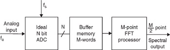
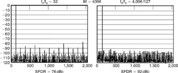
In most applications, the input to the ADC is a band of frequencies (usually summed with some noise), so the quantization noise tends to be random. In spectral analysis applications (or in performing FFTs on ADCs using spectrally pure sinewaves see Figure 6-121), however, the correlation between the quantization noise and the signal depends on the ratio of the sampling frequency to the input signal. This is demonstrated in Figure 6-122, where an ideal 12-bit ADCs output is analyzed using a 4,096-point FFT In the left-hand FFT plot, the ratio of the sampling frequency to the input frequency was chosen to be exactly 32, and the worst harmonic is about 76 dB below the fundamental. The right-hand diagram shows the effects of slightly offsetting the ratio to 4,096/127 = 32.25196850394, showing a relatively random noise spectrum, where the spurious free dynamic range (SFDR) is now about 92 dBc. In both cases, the RMS value of all the noise components is approximately
, but in the first case, the noise is concentrated at harmonics of the fundamental.