Survivability and Traffic Grooming in WDM Optical Networks

Providing detailed coverage of key issues in modern optical networks, this highly useful book provides a framework for dealing with survivability and traffic grooming in wide-area networks.
Figure 19.2 provides a node structure that can be deployed in a light trail framework. In Fig. 19.2, the multiple wavelengths from the input link are demultiplexed and then sent to corresponding light trail switches. A portion of the signal power is directed to the local receiver and the remaining signal power passes through an optical shutter. Such a shutter can be realized using various technologies as an acousto-optic tunable filter (AOTF). Thus, a node receives signals from all wavelengths. If a particular wavelength is not being used by an upstream node (the incoming fiber has no signal), the local host can insert its own signal, otherwise it does not use the trail. The local signal is coupled with the incoming signal as shown in Fig. 19.2.
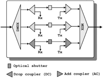
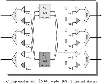
Figure 19.3 provides a detailed light trail node structure with three input and three output fibers and two wavelengths on each fiber. The input signal is first de-multiplexed, a portion of it is dropped, and the remainder goes to the corresponding 3 3 wavelength switch, as depicted in Fig. 19.3. The outputs of the wavelength switches go through the optical shutter and along with the local added signals, are sent to the output ports of the light trail node. Notice that the optical shutter can be located either before the wavelength switch or after it at the output side.