Survivability and Traffic Grooming in WDM Optical Networks
Providing detailed coverage of key issues in modern optical networks, this highly useful book provides a framework for dealing with survivability and traffic grooming in wide-area networks.
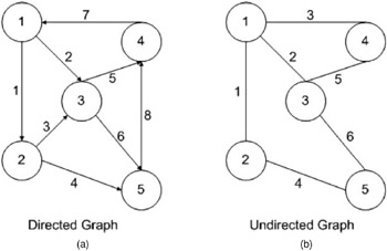
A network is represented by a graph G = ( V, E), where V is a finite set of elements called nodes or vertices, and E is a set of unordered pairs of nodes called edges or arcs [85]. This is an undirected graph. A directed graph is also defined similarly except that the arcs or edges are ordered pairs. For both directed and undirected graphs, an arc or an edge from a node i to a node j is represented using the notation ( i, j). Examples of five-node directed and undirected graphs are shown in Fig. A3.1. In an undirected graph, an edge ( i, j) can carry data traffic in both directions (i.e. from node i to node j and from node j to node i), whereas in a directed graph, the traffic is only carried from node i to node j.
Graph representations. A graph is stored either as an adjacency matrix or an incidence matrix, as shown in Fig. A3.2. For a graph with N nodes, an N N 0 1 matrix stores the link information in the adjacency matrix. The element ( i, j) is a 1 if node i has a link to node j. An incidence matrix, on the other hand, is an N M