Digital Signal Processing Using MATLAB and Wavelets
By Michael Weeks
Chapter 9.5.1 - Example Using Down/Up-Samplers
Intuitively, using up- and down-samplers may seem like it cannot work.
How can we throw out half of our calculations after filtering
without losing information? This section gives a brief example of
how this process works.
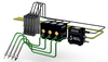
Figure 9.8 shows an example of a two-channel filter bank
with down-samplers followed by up-samplers. The filters are very simple, in fact, these filters would be implemented as in
Figure 8.2, which reduces down to Figure 8.3.
Figure 9.8:
A simple filter bank demonstrating down/up-sampling. |
Since the filter with coefficients {1, 0} allows the input to pass
through to the output, we will replace it with a simple line.
Likewise, we can replace the filter with coefficients of {0, 1} with
a delay unit. With these modifications in place, we have the revised
filter of Figure 9.9.
Figure 9.9:
A simple filter bank demonstrating down/up-sampling, reduced.
. |
Now we are ready to trace an input through to the output, with the
values ![$x[0]$](/RefArticleImages/AC20BF92F42FAE8F4B1DC1261E2AD45F_img146_9.gif) ,
, ![$x[1]$](/RefArticleImages/AC20BF92F42FAE8F4B1DC1261E2AD45F_img147_9.gif) ,
, ![$x[2]$](/RefArticleImages/AC20BF92F42FAE8F4B1DC1261E2AD45F_img148_9.gif) ,
, ![$x[3]$](/RefArticleImages/AC20BF92F42FAE8F4B1DC1261E2AD45F_img149_9.gif) ,
, ![$x[4]$](/RefArticleImages/AC20BF92F42FAE8F4B1DC1261E2AD45F_img150_9.gif) ,
, ![$x[5]$](/RefArticleImages/AC20BF92F42FAE8F4B1DC1261E2AD45F_img151_9.gif) , etc. Keep in mind that
these inputs are listed in order from left to right, so that
enters the filter bank first, followed by , and so forth.
, etc. Keep in mind that
these inputs are listed in order from left to right, so that
enters the filter bank first, followed by , and so forth.
Figure 9.10:
Tracing input to output of a simple filter bank. |
Looking at the top channel of Figure 9.10,
we see the input values go to the down-sampler,
whose output is , , , etc., the even values of  . The
forward transform ends here for this channel, but we will see what this
channel contributes to the output. The up-sampler inserts zeros between
values, to generate the sequence ,
. The
forward transform ends here for this channel, but we will see what this
channel contributes to the output. The up-sampler inserts zeros between
values, to generate the sequence ,  , , , ,
  etc.
Next comes the delay unit, which means that every input to it will appear
at the output one time step later. We note this as a zero for its first
output, followed by the signal that reaches it. The reason for the delay unit
should be apparent when we consider the bottom channel. Thus, the top channel
contributes a signal of , , , , , , etc.,
the even values of with zeros between the values.
etc.
Next comes the delay unit, which means that every input to it will appear
at the output one time step later. We note this as a zero for its first
output, followed by the signal that reaches it. The reason for the delay unit
should be apparent when we consider the bottom channel. Thus, the top channel
contributes a signal of , , , , , , etc.,
the even values of with zeros between the values.
Now we turn our attention to the bottom channel of Figure 9.10.
The delay unit shifts our inputs over one unit, so its first output
is zero, followed by , , ![$x[2],$](/RefArticleImages/AC20BF92F42FAE8F4B1DC1261E2AD45F_img154_9.gif) etc. When this signal reaches
the down-sampler, it has the effect of removing every other value. Since
0 is the first input, it passes through, while is discarded.
Thus, the down-sampler's output is , , ,
etc. When this signal reaches
the down-sampler, it has the effect of removing every other value. Since
0 is the first input, it passes through, while is discarded.
Thus, the down-sampler's output is , , , ![$x[5],$](/RefArticleImages/AC20BF92F42FAE8F4B1DC1261E2AD45F_img155_9.gif) etc. At the
end of the forward transform for the bottom channel, we see that we have
the odd values for . The synthesis side of the QMF for the bottom
channel simply up-samples the signal. This results in the pattern
0, 0, , 0, , 0, etc.
etc. At the
end of the forward transform for the bottom channel, we see that we have
the odd values for . The synthesis side of the QMF for the bottom
channel simply up-samples the signal. This results in the pattern
0, 0, , 0, , 0, etc.
Combining the top channel with the bottom channel with addition results
in  ,
, ![$x[0]+0$](/RefArticleImages/AC20BF92F42FAE8F4B1DC1261E2AD45F_img157_9.gif) ,
, ![$0+x[1]$](/RefArticleImages/AC20BF92F42FAE8F4B1DC1261E2AD45F_img158_9.gif) ,
, ![$x[2]+0$](/RefArticleImages/AC20BF92F42FAE8F4B1DC1261E2AD45F_img159_9.gif) ,
, ![$0+x[3]$](/RefArticleImages/AC20BF92F42FAE8F4B1DC1261E2AD45F_img160_9.gif) ,
, ![$x[4]+0$](/RefArticleImages/AC20BF92F42FAE8F4B1DC1261E2AD45F_img161_9.gif) ,
, ![$0+x[5],$](/RefArticleImages/AC20BF92F42FAE8F4B1DC1261E2AD45F_img162_9.gif) etc.
etc.
This demonstration shows that performing down and up-sampling on the
channels of a QMF is not as crazy as it sounds. In effect, the QMF of
Figure 9.8 breaks the input into its even values and its
odd values, then adds them back together. This results in an output that
matches the input, except for a delay.
© 2026 Infinity Science Press