 | Although DSP has long been considered an EE topic, recent developments have also generated signifi
cant interest from the computer science community. DSP applications in the consumer market,
such as bioinformatics, the MP3 audio format, and MPEG-based cable/satellite television have fueled
a desire to understand this technology outside of hardware circles. Designed for upper division engineering and computer science students as well as practicing engineers,
Digital Signal Processing Using MATLAB and Wavelets emphasizes the practical applications of signal
processing. Over 100 MATLAB examples and wavelet techniques provide the latest applications of DSP,
including image processing, games, fi lters, transforms, networking, parallel processing, and sound. The book also provides the mathematical processes and techniques needed to ensure an understanding
of DSP theory. Designed to be incremental in diffi culty, the book will benefi t readers who are
unfamiliar with complex mathematical topics or those limited in programming experience. Beginning
with an introduction to MATLAB programming, it moves through filters, sinusoids, sampling, the Fourier
transform, the z-transform and other key topics. An entire chapter is dedicated to the discussion
of wavelets and their applications. A CD-ROM (platform independent) accompanies the book and
contains source code, projects for each chapter, and the fi gures contained in the book. FEATURES: - Contains over 100 short examples in MATLAB used
throughout the book
- Includes an entire chapter on the wavelet transform
- Designed for the reader who does not have extensive
math and programming experience
- Accompanied by a CD-ROM containing MATLAB
examples, source code, projects, and fi gures from
the book
- Contains modern applications of DSP and MATLAB
project ideas
|
 TABLE OF CONTENTS
Digital Signal Processing Using MATLAB and Wavelets
By Michael Weeks
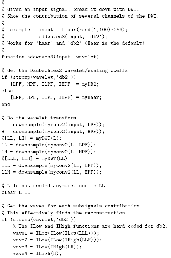
Chapter 9.6 - Breaking a Signal Into Waves
Just as the discrete Fourier transform breaks a signal into
sinusoids, the discrete wavelet transform generates "little waves"
from a signal. These waves can then be added together to reform
the signal. Figure 9.13 shows the wavelet analysis
for three octaves on the left, with the standard synthesis (reconstruction)
on the right. "LPF" stands for lowpass filter, while "HPF' means
highpass filter. The "ILPF' and "IHPF' are the inverse low- and
highpass filters, respectively. Although the down-sampling and up-sampling
operations are not explicitly shown, they can be included in the filters
without loss of generality.
On the right, there is an implied addition when two lines meet.
Figure 9.14 shows an alternate way to do the reconstruction.
While not as efficient as Figure 9.13, it serves to demonstrate
the contribution of each channel.
Figure 9.13:
Wavelet analysis and reconstruction. |
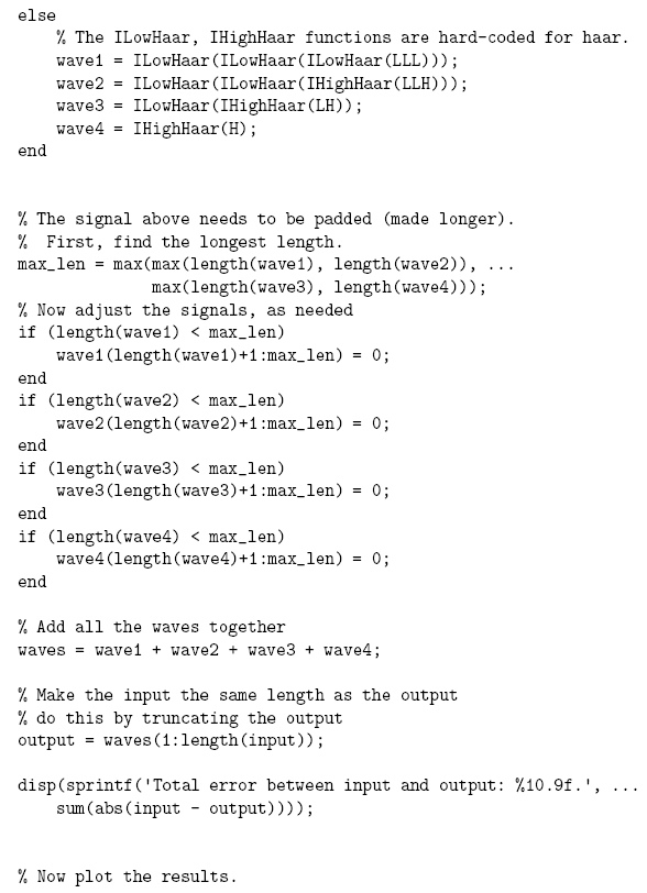
In the end, we have four signals:
three detail signals, and one level-3 approximation.
Figure 9.14:
Alternate wavelet reconstruction.
. |
This section rests on the argument that we can rearrange the operations
in the reconstruction, i.e.,
that we can perform the up-sampling and filtering first,
and then do the addition. We know that the ILPF and IHPF are made with
FIR filters that have constant filter coefficients and are, therefore, linear.
Thus, we know that it does not matter whether we add two signals
together and filter their sum, or filter the two then add the results together.
But what if we have down and up-samplers in the analysis and
reconstruction? Specifically for our purposes here, does it matter if
we up-sample two signals first, then add them together,
as opposed to adding them together, then up-sampling their sum?
For simplicity, let's call the two signals  and
and  , and consider
only the first four samples of each. If we add these signals, we get:
, and consider
only the first four samples of each. If we add these signals, we get:
![\begin{displaymath}[x_0 + y_0, x_1 + y_1, x_2 + y_2, x_3 + y_3]. \end{displaymath}](/RefArticleImages/AC20BF92F42FAE8F4B1DC1261E2AD45F_img213_9.gif)
Next, we up-sample this result to get:
![\begin{displaymath}[x_0 + y_0, 0, x_1 + y_1, 0, x_2 + y_2, 0, x_3 + y_3, 0 ]. \end{displaymath}](/RefArticleImages/AC20BF92F42FAE8F4B1DC1261E2AD45F_img214_9.gif)
Now consider what happens if we up-sample each signal first,
then add them. After up-sampling them, we have:
![\begin{displaymath}[ x_0, 0, x_1, 0, x_2, 0, x_3, 0]\end{displaymath}](/RefArticleImages/AC20BF92F42FAE8F4B1DC1261E2AD45F_img215_9.gif)
and
![\begin{displaymath}[ y_0, 0, y_1, 0, y_2, 0, y_3, 0]. \end{displaymath}](/RefArticleImages/AC20BF92F42FAE8F4B1DC1261E2AD45F_img216_9.gif)
If we add them together now, we get:
We see that this exactly matches the result from adding first,
then up-sampling. Also, the above argument works for arbitrary
lengths of and . Also note that we can recursively apply
this reasoning and conclude that the reconstructions
shown in Figures 9.13 and 9.14 are equivalent.
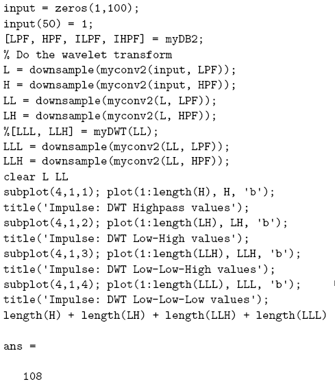
In Figure 9.15, we see the four signals that, when
added together, reform the impulse function. Figure 9.16 shows another four waves that reform the impulse function when added.
The difference between these two is the wavelet used;
in Figure 9.15, we used the Haar wavelet, while
we used the Daubechies-2 (db2) wavelet in Figure 9.16.
Both of these figures show how the DWT represents the input signal as
shifted and scaled versions of the wavelet and scaling functions. Since
we use an impulse function, the wavelet function appears in the "High wave'
signals, while the scaling function appears in the "Low wave' signals
(or the "Low-Low-Low wave' signals in the case of these two figures).
It may be difficult to see from the figure
that these four signals do cancel each other out. To make this easier,
Table 9.1 shows the
actual values corresponding to the plots shown in
Figure 9.15.
The impulse signal used has 100 values, all of which are zero except
for a value of 1 at offset 50. Rather than give all values in the
table, we leave out the zeros and just show the values in the range
49 to 56. As the reader can verify, all columns of this table add to
zero except for the second column. Belonging to the offset 50, the sum of this
column is 1 just as the original impulse signal has a 1 at offset 50.
Figure 9.17 shows the input (impulse function)
versus the output. As expected, the output signal exactly matches
the input signal.
A more typical example is seen in Figure 9.18,
a signal chosen because it clearly shows the Haar wavelets in the
first three subplots. (The example array {9,  , 5, , 7,
  , 4,
, 4,  }
was used here.)
The top plot shows four repetitions of the Haar
wavelet, each of a different scale. The second subplot shows
two repetitions, but these are twice as long as the ones above it.
In the third subplot, one Haar
}
was used here.)
The top plot shows four repetitions of the Haar
wavelet, each of a different scale. The second subplot shows
two repetitions, but these are twice as long as the ones above it.
In the third subplot, one Haar
Figure 9.15: Impulse function analyzed with Haar.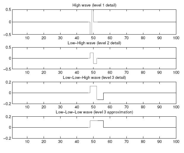 |
Table 9.1:
Impulse function analyzed with Haar.| -0.5000 | 0.5000 | 0 | 0 | 0 | 0 | 0 | 0 |
| 0.2500 | 0.2500 | -0.2500 | -0.2500 | 0 | 0 | 0 | 0 |
| 0.1250 | 0.1250 | 0.1250 | 0.1250 | -0.1250 | -0.1250 | -0.1250 | -0.1250 |
| 0.1250 | 0.1250 | 0.1250 | 0.1250 | 0.1250 | 0.1250 | 0.1250 | 0.1250 |
Figure 9.16:
Impulse function analyzed with Daubechies-2.
 |
Figure 9.17:
Impulse function (original) and its reconstruction. |
wavelet is seen, twice the length of
the wavelets above it.
In these subplots, we can clearly see the wavelet shifted
(along the x-axis) and
scaled (subplots 2 and 3 are products of both the wavelet and
the scaling function).
The final subplot contains the approximation,
clearly the result of several applications of the scaling function.
All of the wavelet-domain values for this particular signal are
positive. This means that all of the wavelets are easy to spot.
With a negative scaling value, the corresponding
Haar wavelet would appear flipped around the x-axis.
Figure 9.18:
Example function broken down into 3 details and approximation. |
An interesting comparison is between the DWT and DFT
for the impulse function. Notice how the impulse function results
in waves that are compact. Almost all of the wave values outside
of the range 40:60 are zero. The Fourier transform, however, needs
many more values to represent such a signal. Since the impulse function
is well localized in time, it is spread out over the frequency-domain.
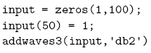
The following code shows an example run of the DWT waves program.
If we use similar code to examine the Fourier transform, we would have
something like the code below.
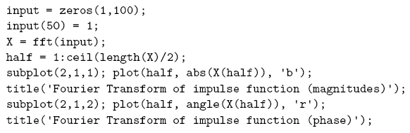
Figure 9.19 shows the results of this code. Notice how
all of the magnitudes are 1, and all of the phase angles are different.
This means that we have to use 50 different sinusoids with 50 different
phase angles to encode the impulse function. We could store the 50 magnitudes
compactly, since they are all the same value, but this is still a lot of
information to remember. Note that the number 50 is specific to this example,
and comes directly from the original signal being a real-valued impulse
of 100 points. If we repeat this experiment with, say, 1000 points
(all except one of which are 0), we would end up with
500 sinusoids to keep track of.
To make this comparison fair,
we will examine the DWT of the impulse function in wavelet space, that is,
after the analysis (left half of Figure 9.13). Thus, we
will use the following code.
As we see from Figure 9.20, most of wavelet-domain
values are zero. From the addition of lengths, the total number of values
that we have to keep is about the same for the DWT as for the FFT
(108 versus 100). But since most of the wavelet-domain values are zero,
we can store this information much more compactly. In fact, examining the
wavelet-domain values reveals that only eight are nonzero!
From this we can conclude that some signals can be stored more
efficiently in the wavelet-domain than in the frequency-domain. Of
course, it depends on the signal; those well localized in time will have
a more efficient wavelet representation, and those well localized in
frequency will have a more efficient frequency representation.
Another example of the DWT versus the FFT shows the opposite extreme.
If we let the input function be a pure sinusoid, and repeat the above
analysis, we see that it is easy to represent in the Fourier-domain.

After performing the FFT on this signal, we see that there is only one
nonzero magnitude. While the FFT will return phase angles that are nonzero,
only the one that corresponds to the nonzero magnitude is significant.
Thus, we have only two values to remember to reconstruct this signal from
the frequency-domain.
Looking at the same signal in the wavelet-domain, we find that all 108
values are nonzero. This confirms what we suspected above: that the
optimal representation of a signal depends upon the signal's characteristics.
Both the Fourier transform and the wavelet transform have a place
in signal processing, but signals will likely be represented more efficiently
by one transform than the other.
Figure 9.19: Impulse function in Fourier-domain.
 |
Figure 9.20: Impulse function in Wavelet-domain. . |
The following program created the graphs of waves above.
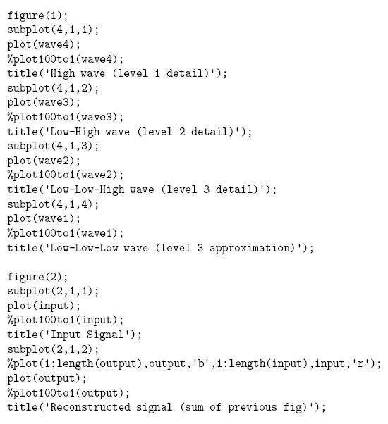
The program calls either the built-in plot function, or the
special plot100to1 program for the output figure, depending
on which lines are commented out. The plot100to1 program makes
the Haar wavelets look their best, since it plots 100 points for every
1 original point, as the name implies. This results in a graph that has
sharper transitions, such as shown in Figure 9.15.
© 2026 Infinity Science Press