The term reverse indicator is synonymous with indicator reverse, reverse rim, and reverse dial. It refers to a method of acquiring lateral offset measurements of two shafts that are approximately coaxial. The generic setup is shown in Fig. 6.1.
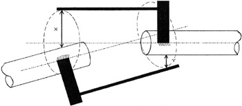 Figure 6.1: Generic reverse-indicator setup.
 The two values, x and y, are typically acquired with mechanical dial indicators, but could be electronic or optical distance-measuring devices. The method was first used with dial indicators, but now the term reverse indicator is descriptive of the method of obtaining the numbers x and y, rather than the measuring devices themselves. Today, all laser alignment systems use the reverse-indicator method or one of its variations.
Setups
There are three basic measuring setups to acquire knowledge about the shaft orientations:
-
Reverse indicator
-
Face-and-rim
-
Forcados method
All of these employ two dial indicators. The face-and-rim method is covered in the next chapter. The Forcados method is covered at the end of this chapter and again in Chapter 11, "Drive Shafts." Variations to these three basic setups are covered at the appropriate time.
Figure 6.2 shows the basic reverse-indicator setup. The key features of this setup are two clamps, one on each shaft, two dial indicators, and two extension bars. The dial indicators do not need to be 180 apart. They can be on the same side, or at any angular orientation to each other. They function independently. It is entirely permissible to take one set of dial readings,...
Copyright The McGraw-Hill Companies, Inc. 2000 under license agreement with Books24x7