Ferrite Beads Information
Last revised: October 30, 2024
Reviewed by: Scott Orlosky, consulting engineer
Ferrite beads are used to suppress unwanted signals that can interfere with electrical devices such as DC supplies, transmission lines and cables. They provide attenuation of selected frequency bands.
The physical shape of ferrite beads is similar to a toroidal inductor, but the beads have a greater length to diameter ratio and usually a greater outside to inside diameter ratio than most toroid cores. Different size / shape beads of the same material have different degrees of suppression.
The type of ferrite material used to manufacture the bead determines the range of frequencies for suppression purposes, and the physical size and shape of the bead determines the amount of attenuation. In general, the impedance is directly proportional to the length of the ferrite beads.
Specifications
Important general specifications to consider when searching for ferrite beads include technology, form factor, beads in package, and packing method.
Technology
Choices for technology type include:
- Solenoidal (standard) core — Solenoidal cores are rod-shaped cores.
- Toroidal — Toroid inductors have a doughnut shape and come in various diameters, thickness, permeability and types depending upon the frequency range of interest. They have a high inductance for the physical space occupied.
- Bobbin core — A bobbin core is an inductor with a core with the shape of a bobbin or spool. Bobbin cores are available with and without leads and in the axial and radial form.
- Wirewound — A wirewound inductor is an inductor with a core made of wound wires.
- Multilayer — Multilayer inductors are inductors constructed by layering the coil between the layers of core material. The coil normally consists of a bare metal material (no insulation). This technology is normally referred to as "non-wirewound". The inductance value can be made larger by adding additional layers for a giving spiral pattern.
- Laminated — Laminated inductors are ferrite beads with a core that is constructed by stacking multiple laminations on top of each other. The laminations can be of a variety of materials and thicknesses.
Form Factor and Number of Beads

Form factor choices include rod, beads on leads, bar, plate, tube, and chip:
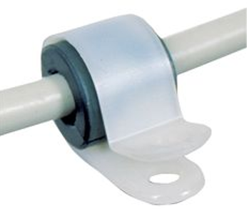
- Beads on leads — The bead has radical leads.
- Plate — The bead is in the shape of a bar.
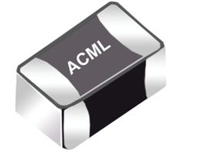
- Chip — The bead is bult in a chip using semiconductor materials.
- Rod — The bead is in the shape of a cylindrical rod.
- Bar — The bead is in the shape of a bar.
- Tube — The bead is in the shape of a hollowed tube.
The number of ferrite beads in the package can be 1, 2, or 4.
Packaging
Choices for packing methods include tape reel, tray, tube, and bulk pack:
- Tape reel — Components are packed in tape reel assemblies that include a carrier tape with embossed cavities for storing individual components. A cover tape seals the carrier tape in place. This composite tape is then wound on a reel that is placed in a corrugated shipping box for transport and delivery. Customers unpack the reels and load them into industry-standard, pick-and-place board assembly equipment.
- Tray / rail — Components are packed in trays (rails) that are made of carbon-powder or fiber materials and molded into rectangular outlines that contain matrices of uniformly spaced pockets. These containers protect components during shipping and provide proper component location and orientation for use with industry-standard, pick-and-place board assembly equipment. Trays are designed for components for that have leads on four sides and that require component lead isolation during shipping, handling, or processing.
- Tube — Components are packed in shipping tubes or stick magazines that are made of rigid polyvinylchloride (PVC) and extruded in industry-standard sizes. These containers protect components during shipping and provide proper component location and orientation for use with industry-standard, pick-and-place board assembly equipment.
- Bulk pack — Components are distributed as individual parts.
Performance Specifications
Important performance specifications to consider when searching for ferrite beads include impedance range, impedance tolerance, impedance testing frequency, DCR (DC Resistance), rated DC current, and operating temperature:
- Impedance is the total resistance to the flow of current, including AC and DC components.
- DC component is simply the DC resistance of the device.
- AC component includes the bead reactance.
- Impedance tolerance is the allowed amount of variation from the nominal value as specified by the manufacturer.
- Impedance testing frequency is the frequency at which the bead impedance is tested.
- Direct current resistance is the resistance of the inductor winding measured using DC current. The DCR is most often minimized in the design of an inductor and specified as a maximum rating.
- Rated DC current (IDC) is the level of continuous direct current that can be passed through the inductor with no damage. The DC current level is based on a maximum temperature rise at the maximum rated ambient temperature.
- Rated current is related to the inductor's ability to minimize the power losses in the winding by having a low DC resistance. For low frequency currents the RMS current can be substituted for the DC rated current.
- Operating temperature for ferrite beads is the full required range of ambient operating temperature.
Ferrite Beads FAQs
What is the impact of DC bias on ferrite bead impedance?
The DC bias on ferrite bead impedance is an important consideration. The DC component of impedance in ferrite beads is essentially the DC resistance of the device. This resistance is a critical factor in the design of an inductor and is often minimized to ensure efficient performance.
Ferrite beads are typically operated under current bias, which means that measurements with DC bias are essential for understanding their performance. The presence of a DC bias can influence the impedance characteristics of the ferrite bead, potentially affecting its ability to suppress high-frequency noise.
What is the role of ferrite beads in EMI suppression?
Ferrite beads are passive components that are highly effective in suppressing high-frequency noise. They provide high attenuation over a wide frequency range, which helps in reducing EMI in electronic circuits.
One of the advantages of using ferrite beads is that they do not significantly affect the useful component of the signal. This means they can suppress unwanted noise without degrading the performance of the desired signal.
Ferrite beads are commonly connected in series with the power supply or signal source. This configuration helps in filtering out high-frequency noise from the power lines or signal paths, thereby improving the overall EMI performance of the system.
The impedance characteristics of ferrite beads vary with frequency, exhibiting inductive, resistive, and capacitive behaviors at different frequency ranges. This frequency-dependent behavior is essential for their effectiveness in EMI suppression.
While ferrite beads are effective in EMI suppression, improper use can degrade their performance. It is important to consider factors such as temperature and current bias when designing applications with ferrite beads to ensure optimal performance.
What are the frequency characteristics of ferrite beads?
Ferrite beads exhibit different characteristics at different frequency ranges, which can be categorized into three main regions: inductive, resistive, and capacitive.
In the inductive region, the ferrite bead behaves like an inductor, providing impedance primarily due to its inductance.
In the resistive region, the bead's impedance is dominated by resistive losses, which are effective for dissipating high-frequency noise.
In the capacitive region, the bead behaves like a capacitor, which can occur beyond its self-resonant frequency.
At the self-resonant frequency, the impedance behavior of the ferrite bead changes significantly. This is a critical point where the inductive and capacitive reactances cancel each other out, resulting in a purely resistive impedance.
The impedance testing frequency is the frequency at which the bead's impedance is tested to ensure it meets the specified performance criteria.
What are some common applications of ferrite beads in electronic circuits?
Ferrite beads are commonly used in electronic circuits for several applications, primarily due to their ability to suppress electromagnetic interference (EMI) and high-frequency noise. Here are some common applications.
Ferrite beads are highly effective in suppressing high-frequency noise in electronic circuits. They provide high attenuation over a wide frequency range, which helps in reducing EMI.
They are used to maintain signal integrity by suppressing unwanted noise without significantly affecting the useful component of the signal.
Ferrite beads are often connected in series with the power supply lines to filter out high-frequency noise, thereby improving the overall EMI performance of the system.
They are also used in series with signal lines to filter out high-frequency noise, ensuring that the signal remains clean and free from interference.
What are some design considerations when using ferrite beads?
Ferrite beads exhibit different impedance characteristics across frequency ranges, categorized into inductive, resistive, and capacitive regions. Understanding these characteristics is essential for selecting the right bead for your application.
The impedance of ferrite beads can shift with temperature changes. As the temperature increases, the impedance tends to decrease and become more saturated. It is optimal to operate ferrite beads close to ambient temperature (approximately 20°C to 25°C) to maintain stable impedance characteristics.
Ferrite beads are often operated under current bias, and measurements with DC bias are essential for understanding their performance. The presence of a DC bias can influence the impedance characteristics, potentially affecting the bead's ability to suppress high-frequency noise.
The impedance testing frequency is the frequency at which the bead's impedance is tested to ensure it meets the specified performance criteria. This is an important specification to consider when selecting ferrite beads.
The DCR is the resistance of the inductor winding measured using DC current. It is often minimized in design and specified as a maximum rating. Lower DCR values are generally preferred to reduce power loss.
Environmental factors, such as temperature and humidity, can affect the performance of ferrite beads. These should be considered during the design phase to ensure reliable operation under varying conditions.
Ferrite Beads Media Gallery
References
GlobalSpec—White Paper: Behind the Magic of High Frequency SMT Chip Bead Ferrites
Image Credits:
1-Source Electronic Components | Frontier Electronics Corp. |