|
 PREFACE
 TABLE OF CONTENTS
 Chapter 4.4 - Key Building Blocks of a DWDM System
4.4 KEY BUILDING BLOCKS OF A DWDM SYSTEMThe functional domains outlined in the previous section comprise the key functional building blocks of any communications system; domain consolidation depends on actual implementation. As such, purely optical DWDM systems (those that do not convert the optical signal to an electrical signal) consist of physical units that perform the following major functions:
In addition, some major systems perform functionality in the electrical regime, such as control and system provisioning. Thus, the current definition of an "all-optical" system is not exactly "optical" in all aspects, but the term all-optical is limited to the path of the client data-bearing signal as it passes through the system entirely in the photonic regime, whereas all other ancillary functions are in the electrical regime. As a consequence, signal performance monitoring is not easily performed in current all-optical systems, and particularly error detection and correction; error detection may be performed electrically, but it is not very useful if optical correction cannot be performed. Obviously, this presents a challenge and future optical technology will address this as well. To summarize, the key building blocks from a system point of view (depending on system and layer, some functions may not be applicable) are:
4.4.1 Transmitters and Receivers In DWDM systems, the main function of the transmitter is to source a modulated optical signal complying with a set of specifications (as specified by standards and application), a list of which is (those with an asterisk are, in addition, specific to tunable transmitters):
The actual values in this list depend on the application the transmitter is designed for. For example, the bit rate may be as low as several Mb/s or as high as 40 Gb/s. The signal modulation may be nonreturn to zero (NRZ) or return to zero (RZ); the latter may also be 50% RZ or 33% RZ. The output optical power may be specified for short fiber lengths or for long fiber lengths (in all cases, sources must comply with eye safety specifications). Center frequency may be based on a C-band 80-λ grid, on a 40-λ grid, or on a 160-λ C + L-band grid, and for different fiber types (such as SSMF, DSF, and MMF). The main function of the receiver is to detect and respond to a modulated photonic signal with a predetermined level of accuracy, which is measured in bit error rate. The modulated photonic signal has traveled through the fiber and many components so that when it arrives at the photodetector it is already degraded in power, spectral, and noise content. When fiber is many kilometers long, the incident light at the receiver is very weak due to signal attenuation, and a logic "one" contains photons counted in single digit; the minimum number of photons required for a receiver to recognize a logic "one" is known as the quantum limit. At minimum, a receiver consists of an optical preamplifier (optional); a polarization filter (optional); a power equalizer; a focusing lens (preferred); an efficient, fast-responding, and low-noise photodetector; an electronic low pass filter; a circuit that extracts the clock from the incoming signal and determines the time and threshold level for sampling (in on-off keying demodulation); and other components needed to demodulate the signal. In DWDM systems, after the preamplifier, polarizer, and power equalizer, an optical wavelength demultiplexer separates the wavelengths, and each is directed to its receiver either via an optical waveguide, by a short fiber, or directly. Thus, the key characteristics of the DWDM receiver are:
From the transmitter launched power in the fiber (Tx) and the receiver sensitivity (Rs), the maximum allowable loss is calculated (Lossmax): Lossmax = Tx – Rs (dB) For example, if Tx = 0 dBm and Rs = –20 dBm, then Lossmax = 0 – (–20) = 20 dB; remember that we can subtract dBms yielding a difference in dBs (Chapter 2). The maximum allowable loss helps determine the optical path span, the required amplification gain, and the needed compensation. 4.4.1.1 Modulation and Demodulation of the Optical Signal Modulation is the action of temporally altering one or more of the parameters of the photonic signal. In optical communications, these parameters are phase, frequency, and amplitude of an optical carrier or wavelength. When the phase is modulated, the method is called phase-shift keying (PSK); when the frequency is modulated, it is called frequency-shift keying (FSK); and when the amplitude is modulated, it is called amplitude-shift keying (ASK). The latter case includes the intensity modulation with direct detection (IM/DD) and the on-off keying (OOK) modulation method. In optical communications, the modulation method plays a key role in:
Coherent heterodyne and homodyne detection techniques were initially developed for radio communications. In optical transmission, the term coherent indicates that another light source is used as the local oscillator at the receiver; optical coherent methods improve receiver sensitivity by approximately 20 dB, allowing longer fibers to be used (by an additional 100 Km at 1.55 μm). In addition, using IM/DD the channel spacing is on the order of 100 GHz; with coherent techniques it can be as small as 1 to 10 GHz. A metric of good line coders (for 10 Gb/s) is an acceptable eye diagram at the receiver (see Chapter 2) such that the uncertainty of the state (1 or 0) of the received bits is less than 1 bit per second per Hertz (<1 b/s/Hz). Optical communications systems are designed with error rates (as specified in ITU-T standards) at less than 10–12 BER.  Figure 4.8 Coherent detection requires a low-noise local oscillator with narrow linewidth comparable to or better than the incoming optical signal.
Coherent detection of an incoming modulated signal uses a local oscillator (i.e., a light source of a frequency in the vicinity of the transmitted source), which must have a narrow spectral (line) width comparable to that of the source (Fig. 4.8). In addition, the local oscillator must have low noise characteristics; otherwise the spontaneously emitted light adds to noise and the method is not practical. Therefore, amplitude of the local oscillator in coherent receiver design is important. In the case of IM/DD, the incoming signal is directly coupled into the detector, thus eliminating the coupler and the local oscillator. 4.4.1.2 Line Coding Techniques Several coding techniques have been proposed for optical communications: the on-off keying (OOK), the frequency shift keying (FSK), and the phase shift keying (PSK). Currently, the most popular technique is the OOK with return to zero (RZ) or with nonreturn to zero (NRZ). On-Off Keying. This is a modulation method according to which a logic "one" is manifested by the presence of light; similarly, logic "zero" is manifested by the absence of light. When the logic "one" is lighted for the full period (T = 1/f), this OOK is termed nonreturn to zero (NRZ), and when for a fraction of the period (such as 1/3 or 1/2), it is termed return to zero (RZ) (Fig. 4.9). The OOK can be used in coherent detection or in IM/DD detection. However, coherent detection requires constant phase. As a consequence, the laser source cannot be directly modulated because this may shift the signal phase. Therefore, in this case, the signal amplitude is modulated externally with a titanium-diffused LiNbO3 waveguide in a Mach-Zehnder configuration or with a semiconductor directional coupler based on electroabsorption multiquantum-well (MQW) properties and structures. Conversely, IM/DD detection does not require constant phase, and thus phase shift is unimportant (however, direct laser modulation may also alter the spectral content of the source). Phase Shift Keying. This method modulates the phase of a light beam (the carrier) at the transitions between logic "zero" and logic "one"; that is, it shifts the phase by 180 degrees while the frequency and amplitude of the signal remain constant during all bits, thus appearing as a continuous light wave. For multilevel PSK, the change may be in increments of 45 degrees (8-levels). PSK is a coherent technique. 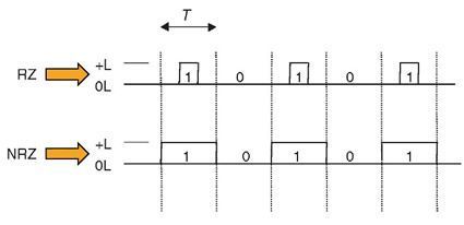 Figure 4.9 OOK RZ and NRZ optical coding. PSK is implemented by passing the light beam through a device that operates on the principle that, when a voltage is applied to it, its refractive index changes; this is known as electrorefraction modulation (ERM). Such devices are made with electro-optic crystals, such as LiNbO3, with proper orientation. The phase difference is expressed by: δφ = (2π/λ)(δn)Lm where the index change δn is proportional to applied voltage, V, and Lmis the length over which the index changes by the applied voltage (Fig. 4.10). Frequency-Shift Keying. This method modulates the frequency ω of a light beam (the carrier) at the transitions between logic "zero" and logic "one"; that is, it shifts the frequency while the amplitude of the signal remain constant during all bits. At the transitions, the frequency changes by Δf, f + Δf for logic "1," and f – Δf for logic "0." Thus, FSK is a coherent two-state (on-off) FM technique. Typical frequency changes are about 1 GHz. The total bandwidth of a FSK signal is approximated to 2 Δf + 2B, where B is the bit rate and Δf is the frequency deviation. • When the deviation is large, Δf » B, the bandwidth approaches 2Δf, and this case is known as wideband-FSK. 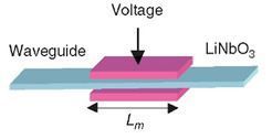 Figure 4.10 PSK modulator: a varying voltage modulates the refractive index of its electro-refractive element and thus the phase of coherent light passing through it. 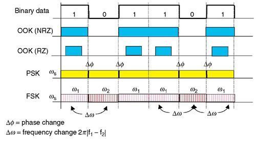 Figure 4.11 Optical modulation methods. • When the deviation is narrow, Δf « B, the bandwidth approaches 2B, and this case is known as narrowband-FSK. A frequency modulation index (FMI), defined by Δf / B = βFM, distinguishes the two cases; wideband-FSK has an FMIβFM» 1 and narrowband-FSK has an FMI βFM« 1. FSK is achieved with electroacoustic Bragg modulators or with DFB semiconductor lasers that shift their operating frequency by 1 GHz when the operating current changes by a mere 1 mA. The small current change required for FSK is viewed positively because it causes a small variation on the optical output power of the laser beam. Thus, DFB semiconductor lasers make very good and fast coherent FSK sources with high modulation efficiency. Figure 4.11 summarizes all shift keying modulation methods. 4.4.1.3 Line Decoding Techniques Optical decoding entails detecting the optical signal and retrieving binary coded information (or demodulate) from the received modulated lightwave, based on one of the three coding techniques:
The employed technique clearly impacts the receiver and demodulator design complexity, but it primarily affects the quality of the received signal and the fiber span. OOK RZ and NRZ Demodulators. On-off keying demodulators use receivers that directly detect incident photons. The number of incident photons in the time domain generates an electrical signal with similar amplitude fluctuation, plus some electrical noise added by the photodetector. When the optical signal has been converted to an electrical signal, amplitude high-frequency fluctuation (and noise) is low-pass filtered. In addition, the signal is sampled at the rate of the expected incoming bit rate by a local phase-locked loop to minimize jitter and signal level uncertainty. Thus, the number of incident photons is interpreted as logic "1" when it is above a threshold level and as logic "0" when it is below that level (see Fig. 2.90). However, there are instances when the incident amplitude is ambiguous due to excessive noise and jitter (manifested by a corrupted eye diagram), and an erroneous 1 or 0 may be produced. OOK modulation/demodulation may be return to zero (RZ) or nonreturn to zero (NRZ), see Figure 4.15. It should be noted that a NRZ signal provides photons for the full duration of the bit period, whereas a RZ signal for a percentage of the period. Popular percentages are 33%, 40%, and 50%. The NRZ or RZ modulation, and the percent, is particularly important in ultrahigh bit rates such as 10 or 40 Gb/s. For example, a 50% OOK 40 Gb/s signal has logic "1" illuminated for 12.5 ps, whereas a 33% for 8.25 ps, that is a reduction by 34%. All other things being equal, this reduction is significant in the amount of received power and thus in the received bit error rate. However, if the path is engineered and budgeted correctly, the RZ peak power is higher, provides better noise isolation, and thus improves the overall optical signal-to-noise ratio. PSK and FSK Demodulators. PSK and FSK demodulation is based on coherent detection; that is, in addition to the received optical signal from the fiber, one or two local (optical) oscillators are required to interferometrically interact with the received optical signal and convert it to OOK. The received PSK modulated optical signal, ωS, is mixed coherently with a locally generated laser light, ωLO, and because both are of the same frequency, they interact interferometrically (Fig. 4.12), so that when both frequencies are in phase, there is constructive contribution, and when they are not in phase, destructive, and thus (ideally) an on-off keying signal is generated. Since the accuracy of this method depends on the phase variation of the signal, phase stability and low noise are very critical. The basic principle of a simplified homodyne FSK demodulator is shown in Figure 4.13. The received FSK modulated optical signal, ωS, is passed through a narrow-band optical filter tuned to pass the frequency ω1 = ω + Δω. Thus, whenever this frequency only passes the filter, the frequency ω2 is rejected and the outcome is equivalent to an OOK modulated signal. Since the accuracy of this method depends on the frequency variation of the signal, no frequency shift (high frequency stability) and low optical noise are very critical. 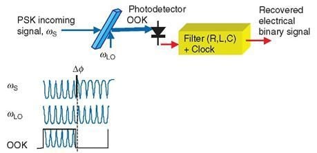 Figure 4.12 Principles of a homodyne PSK demodulator.  Figure 4.13 A simplified FSK demodulator. |