|
 PREFACE
Chapter 4.4.3 - Dispersion Compensating Solutions
4.4.3 Dispersion Compensating Solutions
4.4.3.1 Chromatic Dispersion Compensators
We have discussed (in Chapter 2) at least two components that compensate for dispersion, the chirped fiber Bragg grating and the chromatic dispersion compensating fiber (DCF). DCFs have been designed with a relatively large core effective area (about 20 mm2) and such that shorter wavelengths travel slower than longer (that is, the opposite of single mode fiber) thus having a negative dispersion (a typical value is –100 ps/nm-km). However, DCFs have also more fiber loss (about 0.5 dB/km). Therefore, although DCFs compress the widening of a pulse, they also cause signal loss that must be compensated for with amplifiers (Fig. 4.21); a 5-km DCF may cause 2.5-dB losses.
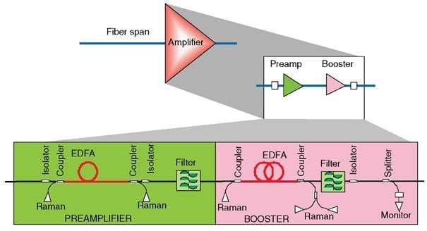
Figure 4.20 A look inside a possible regenerator (redundancy is not shown).
Based on this, dispersion compensating modules (DCM) have been engineered that are used in systems and/or in regenerators to help increase the span of fiber (Fig. 4.22).
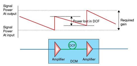
Figure 4.21 Dispersion compensation fiber and amplification action.

Figure 4.22 Dispersion compensation action.
It is typical that DCMs use Raman pumps in DCFs to both compensate for dispersion and amplify the signal. In this case, Raman amplification and DCF fiber loss counteract. The net DCM gain is obtained by adding the desired Raman gain at the output of the DCM plus the internal DCM losses, and if more that one pump is used, plus a margin to compensate for Raman ripple and perhaps an equalizer. The net gain then is estimated from
Net DCM gain = desired R – gain + internal DCM losses + margin (dB)
For example, if a desired Raman gain is 6 dB (calculated based on fiber type, span, power launched in the fiber, and receiver sensitivity), the internal DCM losses are 10 dB (this accounts for DCF and splices and connector losses), and the margin is set at 2 dB, then
Net DCM gain = 6 + 10 + 2 = 18 dB
Although every effort is made to match DCM's negative dispersion slope with the chromatic dispersion slope as much as possible, in reality DCMs do not reduce dispersion to exactly zero but there is always a small amount of dispersion at the output of a DCM. This becomes particularly significant in fiber paths with several DCMs because residual dispersion is cumulative and puts a limit on the number of DCMs in the path (Fig. 4.23). In addition, the uniformity of dispersion compensation is expressed by normalizing the DCM's dispersion slope at a wavelength selected at about the middle of DCM's spectral range. Thus, based on the normalized compensation, the compensation variability of other wavelengths in the spectral range is expressed as a percent (e.g., 95% or 105%); plotting the compensation variability per wavelength, a relative dispersion slope (RDS) is defined.
Another limiting factor in dispersion is long paths with optical add-drop multiplexers (OADM). The reason is that the dispersion characteristics of a dropped signal and an added are not the same. Figure 4.24 illustrates the latter point for the best and worst cases.
4.4.3.2 Polarization Mode Dispersion Compensators
As described in Chapter 1, polarization mode dispersion (PMD) is the polarization dependency of each wavelength in a "chromatic" signal (the spectral content) due mainly to chemical and geometry imperfections of the fiber core. Although polarization change is very small, as the signal travels along the fiber, the change is cumulative and may become significant. For example, if a fiber has a PMD coefficient equal to 0.12 ps/![]() , it takes 100 km fiber to raise PMD to 10 times that (i.e., only 1.2 ps). However, for 1,000 km fiber length, the cumulative PMD is high at 38 ps. If we compare these numbers with the period of a 40 Gb/s pulse (i.e., 25 ps), the need for PMDC is clear: PMDC is unimportant for 100 km but is very important for 1,000 km.
, it takes 100 km fiber to raise PMD to 10 times that (i.e., only 1.2 ps). However, for 1,000 km fiber length, the cumulative PMD is high at 38 ps. If we compare these numbers with the period of a 40 Gb/s pulse (i.e., 25 ps), the need for PMDC is clear: PMDC is unimportant for 100 km but is very important for 1,000 km.
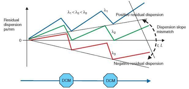
Figure 4.23 Residual dispersion in a path with DCMs.
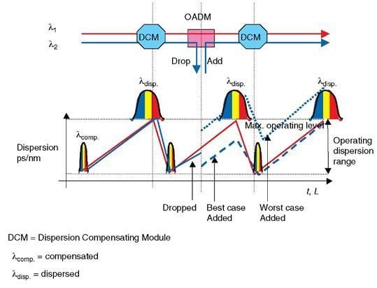
Figure 4.24 Dispersion compensation & OADM.
As a consequence, PMD is a contributor that for short distances (<500 km) and for low bit rates (<10 Gb/s) is insignificant as compared to chromatic dispersion (~0.5 ps/nm-km). Therefore, in such cases, polarization mode dispersion compensation (PMDC) is not contemplated. However, at very long fiber lengths and bit rates at or exceeding 40 Gb/s, PMD becomes significant; even the fiber temperature may become significant, and thence whether the fiber is underground or aerial. In this case, PMDC is included in the design of dispersion compensating modules.
PMDC is accomplished by using strongly polarized fiber that in practice "overshadows" the polarization states of the signal. PMDC modules still have a residual PMD, which should not be more than half ps and a PDL of more than a tenth of a dB.