|
 PREFACE
Chapter 4.7 - Fault Detection and Reporting Strategy
4.7 FAULT DETECTION AND REPORTING STRATEGYFaults at different levels of the traditional optical network have been thoroughly studied. Fault monitoring, detection, triggers, actions, reporting, and restoration scenarios have been defined in standards (e.g., STM, SONET/SDH, and ATM). However, as the multiwavelength optical transport network (DWDM-OTN) becomes "all-photonic" and with ever-increasing bit rates, the photonic physical layer fault strategy must be reviewed and updated. Because of the huge amount of data rate passing a node, faults should be detected as soon as they occur (within nanoseconds) and should be restored or isolated within less than a millisecond, and when equipment fails (such as a unit) and must be replaced. Unit protection should be incorporated into the system design to allow for uninterrupted service and for the craft personnel to replace the failed unit, which may require hours. The evolution of the DWDM-OTN is predicated on the transport layer functionality to the (physical) optical layer and to a maintenance strategy. Thus, a need arises to:
This list pertains to the optical layer. Indeed, this is the layer that impacts the clients signal mostly. Higher layers are not "optical" but they are rather electronic or software. However, this does not mean that they are less important, as they may also cause failures that impact the client signal or service. As an example, a corrupted database may also corrupt SLA, it may mis-switch a path or it may provision the transmitter or receiver wrongly. Nevertheless, these failures are well understood, and countermeasures have already been developed to minimize their probability. From a network layer perspective, fault detection takes place within an administrative domain. In it, the signal integrity is monitored by the node at its inputs and is compared with an expected value. In general, fault detection, testing, and restoration are preferred to be service nonintrusive. Currently, nonintrusive testing in the optical regime is difficult; however, the level of development activity in optical sensors increases and this will not be the case in the near future. Typically, the received optical signal is monitored for:
4.7.1 Fault Detection on the Network Level When a failure condition is detected, it is communicated to the network management entity responsible within that domain. It is also communicated to the neighboring nodes to inhibit them from false failure detection and reporting. For example, when a node experiences a failure that impacts the client signal, all nodes downstream of the path may experience the same failure. The network management entity initiates remote testing, fault correlation, fault locating, isolation, and restoration or protection procedures. The node will execute all service restoration actions and communicate the results to management. As a consequence, architecting an effective DWDM transport network requires that many critical factors be considered, such as:
4.7.2 Fault Detection Identifiers From an end-to-end perspective, the signal carries overhead information. This is included by the source end terminal to communicate with the destination end terminal. The client does not "see" this overhead. Some of this overhead is:
4.7.3 Overhead, Data, and Error Correction: The Digital Wrapper The SONET frame consists of two fields, one that contains overhead and one that contains client data (see Chapter 3). The SONET overhead is also partitioned into section, line and path related overhead data. In the overhead, there are bytes, which provide a mechanism for error control. Error control implies that a number of errored bits in the signal are detected, Ed, and a number of errored bits are corrected, Ec; typically, Ec < Ed. However, the error control achieved with few bytes in the SONET overhead first does not provide a sufficiently powerful correction or a very fast corrective mechanism, which is required by ultrahigh bit rate optical signals and particularly DWDM signals. In ultrafast DWDM signals (10 to 40 Gb/s), there is a strong relationship of the optical signal to noise ratio (OSNR) with bit-error-rate (BER) and the received optical power, or the optical penalty at the receiver (see Chapter 2). In general, the more degraded the OSNR, the more the penalty and thus the higher the BER. As a consequence, the fiber span between transmitter and receiver (without signal restoration in between) must be shorter to support the expected quality of signal and quality of service. For example, OSNR increases by approximately 5 dB each time the bit rate quadruples; for example, at 2.5 Gb/s OSNR is approximately 10 x 10–10 dB, at 10 Gb/s is approximately 15 x 10–10 dB, and at 40 Gb/s is approximately 20 x 10–10 dB. This clearly affects the receiver sensitivity, which at 2.5 Gb/s is below –40 dBm, and at 40 Gb/s puts a penalty by more than 10 dBm. As a result, the transmitter requirements are also affected from below 5 dB (at 2.5 Gb/s) to approximately 10 dB (at 40 Gb/s). However, in many long-haul applications it is desirable that the fiber span be as long as possible. To ensure that the quality of signal at the receiver will be at the expected level, a strong error correction code is added, which, by virtue of correcting the number of errors in the signal, effectively allows for longer fiber. Such strong error correction code is the forward error (detection and) correction, or FEC. Such FECs have been used extensively in submarine applications (see, e.g., ITU-T recommendation G.975, "Forward Error Correction for Submarine Systems," November 1996). As an example, the TAT-14 transatlantic submarine cable network launched in September 1998 (by a consortium of more than 50 telecommunications companies) links the United States to Denmark, France, Germany, the Netherlands, and the United Kingdom. Such multimillion or more than billion dollar projects are designed to meet the exponential growth in transatlantic traffic due primarily to fast-expanding demand for data, Internet, and multimedia services. Table 4.4 illustrates the performance of an FEC by listing some BER values before and after FEC. A poor signal with BER at 10–4 has been FEC-improved to a high-quality signal with BER 2 x 10–13 (communications systems require a minimum of 10–12). The structure of an error detecting and error correcting code based on a Reed-Solomon error correction code is illustrated in Figure 4.40. This code is annotated as RS(255,239,17), where the numbers in parentheses indicate that the total length is 255 bytes, 139 of which are data. This code is able to detect 16 errors and correct 8 errors.  Figure 4.40 Example of a RS(255,239,17) Reed-Solomon error correction code n/k; (n = 255, k = 239 and 2t + 1 = 17). In optical transport networks (long-haul), the fundamental philosophy of SONET protocol frame has been adopted but with a more powerful protocol suitable for ultra-high data rates, known as digital wrapper. The power of the digital wrapper lies in a forward error correction (FEC), tandem connection (TC) functions, path level protection, and higher bandwidth communication channels in the sense of per overhead byte. The basis of the per optical channel frame of the multiwavelength optical transport network is on three blocks; a (1 byte) block of overhead for operations, administration, and maintenance for the optical channel, a 238-byte block of data (the optical channel payload envelope) in which the client-formatted payload is mapped (SONET, ATM, IP, etc.), and of a separate 16-byte block that contains the FEC code (Fig. 4.41). This 255-byte comprises a digital wrapper subframe. Although this subframe with FEC greatly improves the BER, it also adds bandwidth by approximately 7%. This digital wrapper requires no processing pointers (like SONET); it is format-independent; all payload types are acceptable (SONET, IP < FR ATM, etc., even types not defined yet), it supports the ITU-T optical channel OAM functions (see ITU-T recommendation G.872); and it supports end-to-end performance monitoring required for native data services and lease wavelength applications. It also has a constant bit rate, which implies that the client payload must fit into the optical channel payload envelope. On the positive side, 16 subframes define a basic frame called an optical transport unit (OTU) (Fig. 4.42), and four basic frames define a superframe so that the digital wrapper may evolve to accommodate network bandwidth elasticity, and scalability (see ITU-T recommendation G.709). Like SONET/SDH, transmission of the OTU requires that long sequences of "1"s or "0"s be avoided. The latter is ensured only if a suitable scrambler is used. According to ITU G.709, "the operation of the scrambler shall be functionally identical to that of a frame synchronous scrambler of sequence length 65,535," and that "the generating polynomial shall be 1 + x + x3 + x12 + x16." Thus, the probability of data emulating the scrambler and generating a long string of "0"s or "1"s, although finite, is negligible. Scrambling is performed after FEC has been calculated and inserted in the OTU signal (Fig. 4.43). The OTU frame consists of only 4,080 bytes, which is much smaller than 65,535. This implies that the scrambler is reset after the last byte of the frame.  Figure 4.41 The basis of the optical channel digital wrapper.  Figure 4.42 The optical transport unit consists of 16 byte-interleaved subframes. 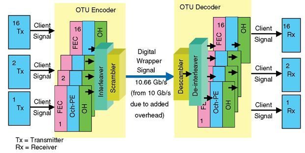 Figure 4.43 OTU basic sequence of events at the transmitter and receiver sides. The digital wrapper defines three sublayers: the path, the tandem connection, and the section. The overhead in an optical channel (OCh) basic digital wrapper frame that provides sublayer features for all three: section (OCh-S), tandem connection (OCh-TC), and path (OCh-P) (Fig. 4.44).  Figure 4.44 Definition of sublayers in the basic optical channel (OCh) frame structure. For example:
|