|
 PREFACE
Chapter 4.9.3 - DWDM Metro Systems
4.9.3 DWDM Metro Systems
DWDM Metro systems consist of network nodes of a physical fiber ring topology (see Fig. 4.3). Connectivity between nodes is achieved via wavelengths (see Section 4.2) so that the logical topology may be a star, a mesh, or purely a ring (see Fig. 4.4).
Depending on the protection strategy, the ring may be single, dual, or quad. Typically, small Metro nodes support a single-fiber ring topology; medium Metro nodes support a two-fiber (dual) ring topology, where one is used for service and the other is used for protection, and large Metro nodes support a four-fiber (quad) ring topology, where two are used for service and the other two are used for protection.
Metro networks have a single-fiber ring if service protection is not an issue or if there is bidirectional traffic; dual-fiber ring if service protection on the optical layer (wavelength) is important; quad if there are two dual rings, one pair for service and one pair for protection. The more aggregate bandwidth on the ring, the more complex the protection method, and the more complex the optical add-drop multiplexer and the node on the ring. In addition, at least two of the nodes on the ring (one a single-fiber ring) are designated as hubs (the second hub is for additional network reliability and protection). Hubs provide connectivity with other similar or dissimilar networks as well as remote access to ring nodes, wavelength management and provisioning via the supervisory channel, as well as node functionality.
In general, a hub accepts various (electrical) payloads (TCP/IP, ATM, STM, LAN, etc.) destined to one or more of its nodes on the ring. Each payload type (channel) is either mapped in another format (e.g., IP over SONET) or sent in its natural form to its corresponding physical interface. From there it is transported over an assigned wavelength, which is multiplexed along with others in the fiber ring. The requirement, complexity, and reliability of the hub are proportional to that of the Metro network.
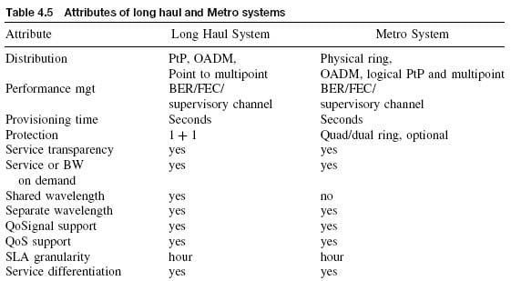
Different Metro networks cover different geographic areas; they have different aggregate bandwidth, performance requirements, service offerings, and complexity and cost structure. That is, Metros are versatile; they offer managed wavelength services and address a wide range in the applications space, and therefore Metro growth has been impressive at an almost exponential rate (~x1.2) per year. Because of this expected growth, most large communications design houses as well as scores of new startups have announced Metro applications and products, which are classified as large, medium, and small Metro. Clearly, large or medium Metro systems and long-haul systems address different needs and services, apart from the common need to transport traffic between two points. The desirable attributes of managed wavelength services offered by Metro and LH systems are listed in Table 4.5.
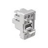
A DWDM Metro node may be thought of as consisting of two sections, an optical add-drop multiplexer and a system attached to it, which may be either all-optical or opaque; this system manages the optical bandwidth and terminates or re-sources the supervisory channel (see Fig. 4.3). In practice, these two parts have been consolidated into one node system, unless the OADM is a single and fixed wavelength for access applications (then the OADM may be a separate entity).
The OADM consists of an optical demultiplexer and an optical multiplexer based on one of the technologies described in Chapter 2, the channel capacity of which depends on the number of wavelengths supported by the ring; thus, it may be as simple as 1:6 or as complex as 1:40. It also consists of a switching fabric, which may be as simple as a 2 x 2 cross-connect or as complex as a 40 x 40 or higher, depending on the path protection strategy (none, 1 + 1, 1:1, 1:N, etc.). The technology of the cross-connect is again one of those described in Chapter 2.
In addition to the optical add-drop multiplexer, there are one or more bidirectional transceivers (at minimum one for a single unidirectional ring, two for a dual ring and four for a quad ring), optionally optical (wavelength) converters to convert the customer-supplied wavelength to the wavelength supported by the ring (typically, a 1,310 nm to a C-band wavelength), filters, connectors and splices and perhaps polarizers, SOAs, and other components. The optical gain and loss of these components determine the power budget (and the driving capability) of the node and its complexity.
Typical EDFA specifications for long-haul applications are listed in Table 4.6.

4.9.3.1 Large Metro Systems
Large DWDM Metro systems are nodes of a quad ring topology. They support 40 to 80 or more wavelengths per fiber, each wavelength at a bit rate of 10 or 40 Gb/s. Such rings cover a large geographic area (greater than 1,000 km in circumference) and interconnect several large cities (Fig. 4.52).
Optical amplification is as complex as that of a backbone or long-haul network, based on OFAs and Raman with dispersion and polarization compensation, including optical equalization; amplifiers are able to support the optical signal for fiber spans in excess of 200 km. Thus, the basic architecture and specifications of a large Metro system (node) is not much different from that of the mesh network node.

Figure 4.52 A typical DWDM large Metro OADM node.
Large Metro systems are able to drop and add a high percentage of the traffic on the ring and to reroute traffic when a service-affecting fault is detected. Thus, they drop and add multiple wavelengths per node, and nodes are remotely and dynamically provisioned and they support wavelength assignment. This obviously impacts the size of the optical cross-connect as well as the technology used.
Large Metro nodes provide bandwidth management, grooming, and bridging functionality [i.e., connectivity with other networks (backbone, other Metros, access, etc.)]. However, as more nodes on the ring interconnect with other rings or networks, the large ring Metro starts looking more like a mesh network or a medium-size backbone.
OAM&P functionality in Metro applications is provided by an additional optical channel (or two for protection) that may be either in the 1,300s nm band or in the low 1,500s nm or in both. The supervisory channel is terminated and re-sourced at each node.
Large nodes are key participants in the service survivability strategy. The level of survivability depends on network fault management, which impacts fault detection strategy, optical cross-connect design complexity, as well as supervisory channel and protocol responsivity. To demonstrate how this impacts the Metro node design, consider the case of a single fault on the working (or service) dual ring. In one scheme, traffic flows on both dual rings simultaneously, and thus, as soon as the fault is detected, the protection ring becomes the working ring (Fig. 4.53A). This scheme, however, uses only one dual ring at a time, committing the bandwidth resources of a dual ring. In another scheme, the working ring is still the same by the largest part of the network, and only the failed ring is bypassed by cross-connecting traffic over to the protection ring; the protection dual ring is used for lower SLA grade, and via loopbacks (LB), service may also continue on the protection ring, but some traffic shedding may also take place (Fig. 4.53B). In a third scheme, both service and protection rings are used for traffic but not at full capacity. Then, using loopbacks on the working ring, service continues to the degree possible and excess traffic is passed onto the protection ring (Fig. 4.53C); some shedding of low-grade traffic may also take place.
On rare occasion, a dual fiber fault may take place (e.g., disaster or when both rings are collocated in the same cable). In this case, the loopback capability of large Metro systems has the ability to bypass the faulty region (Fig. 4.53D).
As seen in Figure 4.52, the design rules of a Metro system may vary; the larger the system, the more aggregate bandwidth it carries and the more important the service protection. Along with the added design complexity in the optical cross-connect, consider amplification, compensation, equalization, provisioning, mechanical, power, heat, and many other issues that all impact the system's complexity.
4.9.3.2 Medium and Small Metro Systems
Medium Metro systems have 40 wavelengths at a bit rate (per wavelength) from 2.5 Gb/s to 10 Gb/s, with channel separation of 100 nm. They are applicable to a geographic area that covers a region of about 500 km in circumference or a regional area with several multilevel buildings (such as skyscrapers in large cities). Amplification is based on less complex OFAs and Raman amplifiers. Dispersion compensation may not be required, but equalization may be needed, and amplifiers are able to support the signal for fiber spans on the order of 100 to 200 km. Such Metro systems are also applicable to enterprise (business) networks with fewer nodes that provide a multiplicity of services and support a variety of traffic types (TDM, SONET/SDH, ATM, IP, etc.). In many respects, medium Metro systems are reduced-capability large Metro systems; in fact, some vendors may offer Metro systems that, depending on configuration, may be applicable either to large Metro networks or to medium Metro networks.

Figure 4.53 Using OXC loopbacks in 4-fiber DWDM large Metro systems.
Small Metro systems have fewer than 40 wavelengths, each at a bit rate (per wavelength) of up to 2.5 Gb/s, with channel separation of 200 nm. Because of this, they are also known as coarse-WDM (CWDM) Metro systems. CDWMs are applicable to small geographic areas of up to 100 km in circumference with few multilevel buildings, large campuses, or several residential neighborhoods. Amplification is simple and compact based on SOAs (and, depending on application and requirements, perhaps on OFAs) so that amplifiers can support the signal for fiber spans of less than 80 km Typically, the transmitter has 0 dBm output power and the receiver is a PIN-type photodetector preferably with no clock and retiming. Because of the small number of wavelengths, CWDMs support few nodes (8-32), and therefore the channel assignment for each node on the ring may be fixed. As a consequence, the optical add-drop multiplexer in each node has a compact, reliable, and simple passive optical technology, such as passive Bragg gratings, rotators, filters, and so on.

Typically, Metro systems with SOA amplification have the requirements listed in Table 4.7.
Similarly, the laser and receiver requirements for Metros are given in Table 4.8.
CWDM demands very inexpensive systems. However, the paramount features of CWDM systems are small physical size, easy maintenance, robustness, and low cost. As simple as these features may seem, in practice they require as few components as possible (no elaborate amplifiers and cross-connects), integration of optical functionality, quality low-cost transmitters and receivers, optical components (filters, connectors, splices, etc.) with very low insertion loss and very small margins. In this case, every tenth of a dB loss counts. A minimal configuration of a simple DWDM OADM node with dual ring Metro is illustrated in Figure 4.54.