|
 PREFACE
Chapter 4.5 - Wavelength Management Strategy
4.5 WAVELENGTH MANAGEMENT STRATEGYIn current DWDM systems, each wavelength is used as a separate channel and thus, the wavelength assignment may be fixed over the complete path (end-to-end) in the network, even if the path is defined over several subnetworks, each managed by a different network (domain) operator (Fig. 4.35). As a side note, the interface between two domains is known as optical network-to-network interface (ONNI) and in optical transport networks (OTN) is known as interdomain interface (IrDI); the interface between two nodes within the same domain is known as intradomain interface (IaDI). This interface defines the communication interface requirements for interoperability and internetworking. To examine what this means, let us consider an opaque system with two fibers in, fIN1 and fIN2, two fibers out, fOUT1 and fOUT2, two wavelengths per fiber λ11, λ12, λ21, and λ22, multiplexers and demultiplexers and a 4 x 4 switching matrix, where λ11 = λ21 and λ12= λ22. Now, we consider two distinct cases. Case A. We want to switch λ11 from fIN1 to fOUT1, λ12 from fIN1 to fOUT2, λ21 from fIN2 to fOUT1, and λ22 from fIN2 to fOUT2. This is a simple case for which there is no wavelength conflict; that is, two same wavelengths are not switched to the same output fiber, Figure 4.36. Case B. We want to switch λ11 from fIN1 to fOUT1, λ12 from fIN1 to fOUT2, λ21 from fIN2 to fOUT2, and λ22 from fIN2 to fOUT1 . This is a typical case for which there is wavelength conflict; that is, two same wavelengths are switched on the same output fiber (for example, λ11 and λ22) (Fig. 4.37). Thus, in order to avoid wavelength conflict, wavelength converters must be used. In Figure 4.37, the wavelength converters (WCn) have been placed at the output of the switching fabric. However, their actual location is a design choice and it depends on the switching technology of the fabric. For example, wavelength converters may be located internal to the fabric, at the outputs (as shown) or at both the input and at the output of the fabric. In the case of fixed wavelength assignment over the complete optical path (Figure 4.35) each node on the path has been provisioned of the input-output-wavelength association. That is, the node "knows" where a wavelength comes from (input) and where it goes to (output). However, in the case of wavelength conversion (or translation), how does the next node on the optical path "know" where the converted wavelength comes from and where it is destined to? And, what if the next node needs to convert the already converted wavelength to another? Figure 4.38 illustrates N signals converted from one wavelength to another as they travel through and are switched by three nodes. Therefore, in DWDM networks the issue of wavelength management arises for the first time, since it was not encountered in legacy single-wavelength optical (such as SONET) or nonoptical systems and networks. In fact, in dynamically wavelength configurable DWDM networks, wavelength blocking may occur as wavelengths are 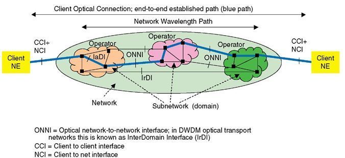 Figure 4.35 An optical path across several subnetwork domains. Each optical link of the path has the same wavelength (shown in blue).  Figure 4.36 DWDM cross-connect and connectivity table; Case A. 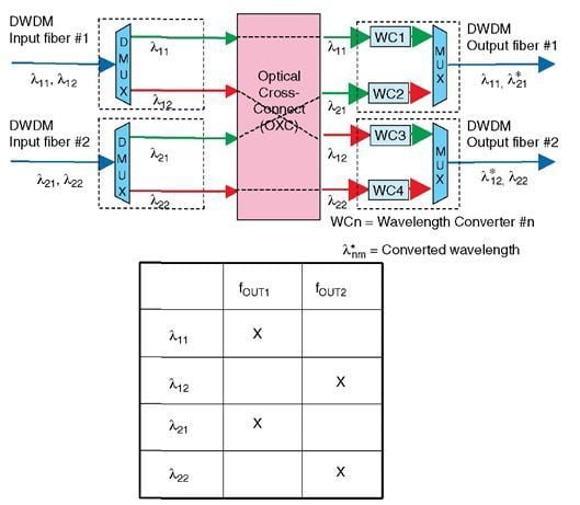 Figure 4.37 DWDM cross-connect and connectivity table; Case B.  Figure 4.38 DWDM channels arriving from a fiber at one wavelength are switched to other fibers as they pass through concatenated cross-connects with converted wavelength. The supervisory channel λSUP remains on the same designated fiber. switched from one fiber to another. To study this, assume K fibers per switching node and N channels (wavelengths) per fiber, each channel lit (or transporting information). Then, there are NXK wavelengths to be switched. In general, there are engineering rules that prescribe the maximum number of wavelengths to be switched from fiber to fiber, such as 50-50. That is, 50% of the channels will pass through express and 50% can be switched. In such case, the problem reduces to switching N x K/2 or N* x K, where N* = N/2; that is, in principle not different that before. Therefore, assuming that N* wavelengths from one fiber were switched to another fiber(s) implies that (N – N*) channels are available to be filled from other fibers. However, there are (K – 1) x N* potential wavelengths contending for the same wavelength space (N – N*), where (N – N*) is much smaller than (K – 1) x N*. Clearly, this is a wavelength contention situation where blocking may occur. In this case, one studies the probability that (K – 1) x N* channels may have the same destination. If the probability is such that P > (N – N*) channels require to be switched on the same fiber with the same destination, then two things may occur: drop the excess wavelengths above (N – N*), a very undesirable case, or pass onto the fiber (N – N*) channels and the remaining on other fibers following a separate path and perhaps switched by another station in the ingress direction. If the next station is not successful, then perhaps the one after the next station may be able to switch channels to the correct destination fiber, and so on. Thus, now the number of stations on the path gets involved in this exercise. Clearly, wavelength translations do not present a technological issue when switches are opaque as all optical signals (wavelengths) are converted to electrical; the system keeps connectivity tables with source and destination identification (ID) codes as well as wavelength values for each incoming signal. In this case, each node on the path "reads" the destination ID and "knows" where to switch to or route the optical signal, assign a wavelength and multiplex many signals in the fiber. However, all-optical nodes are not currently able to optically "read" ID codes off the optical signal without imposing a penalty on the optical signal. This is predominantly addressed with two different strategies, (centralized) network wavelength management and distributed management. In the centralized case, a network wavelength management function provisions each node with wavelength assignments establishing semi-static cross-connectivity over a selected path. Thus, the network wavelength manager "knows" at any time all possible wavelength conversions on a path, whereby each link of the path may have a different wavelength, Figure 4.39. This case depends on a centralized database and algorithm that finds the optimum shortest and bandwidth efficient path with the fewer wavelength conversions. Its speed, however, depends on how fast a path can be established; that is, how fast it can communicate with all nodes, and how fast each node can be provisioned. Clearly, this case implies that all communications interfaces with the various domains are compatible. In the distributed case, there is an additional optical channel that is common to all nodes and over which messages are exchanged. These messages convey input-output-wavelength associations. Thus, optimization of wavelength reassignment is left to each node to execute. This optical channel is also used to communicate from node-to-node additional information. This is known as supervisory channel (SUPV). The supervisory channel is terminated and sourced by each node (see Fig. 4.38), is multiplexed with the client data channels in the same fiber but it has a relatively lower bit rate than data channels (under Gb/s compared with over 2.5 Gb/s), and it may be outside the spectral range of data channels. In addition, it may or may not be protected; supervisory channel protection may be on the same fiber (two independent wavelengths in the same fiber) or it may be on two fibers (two same wavelengths in two different fiber). The supervisory channel conveys messages from node to node very fast and thus it allows for dynamic system reconfigurability. The reconfigurability speed is bounded only by the switching speed of the fabric, by the acquisition time of wavelength converters and other tunable components in the path (such as filters, lasers, etc.), and by time required to communicate the message to the control unit and back (latency) and by the processing time. Dynamic system reconfigurability is required for many reasons, such as system and network upgrades and service restoration.  Figure 4.39 An optical path across several subnetwork domains. Each optical link may have a different wavelength. Network upgrades entail downloading new software versions and new system configurations. During network upgrades it is preferable that service is not affected. Because of component degradation/failure, fiber cuts, excessive additive noise due to nonlinear phenomena, spectral noise, optical power loss, amplification gain drifts and so on, service may be degraded or even lost. Therefore, in order to continue uninterrupted service, systems and networks are architected and designed for service restoration. Service restoration may be on several levels, on the channel, on the fiber, on the node level, and on the network level, and each at various degrees of significance. Service restoration on the channel level implies that a single wavelength has been degraded or lost affecting all traffic transported by the affected channel. A channel may be affected either by the degradation or by the failure of a single component, by excessive induced noise, or by excessive power loss of the optical signal. Service restoration is the action to either remove the affecting cause or to move the channel from one wavelength to another. Service restoration on the fiber level implies that all wavelengths in a fiber are affected either because of a fiber cut or because of component failure that affects all channels. Service restoration is the action to move all channels from one fiber to another. Service restoration on the node level implies that traffic on all fibers at a node are affected because of node failure. Service restoration is the action to move all traffic to other nodes bypassing the faulty node. Service restoration on the network level implies that many nodes in a network have failed; this is also termed disaster failure. Service restoration is the action to move all traffic to other parts of the network bypassing the faulty nodes. The mechanisms for these four levels may be summarized as follows:
However, one issue that must be kept in mind is that, as one wavelength changes to another and new routes are assigned, the optical power budget of the optical path for a particular signal may change, and therefore amplification, dispersion compensation, and equalization become more significant to maintain the quality of signal and the quality of service at the agreed upon levels. |